Danby DOM014401G1 - Manual de uso - Página 2


Índice:
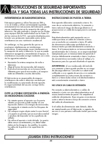
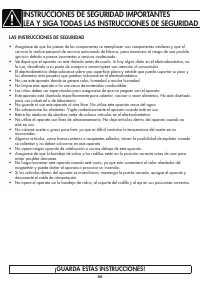
- Página 4 – ¡GUARDA ESTAS INSTRUCCIONES!; INSTRUCCIONES DE PUESTA A TIERRA; ADVERTENCIA; : el uso inadecuado del enchufe; NO UTILICE UN CABLE DE EXTENSIÓN; INTERFERENCIA DE RADIOFRECUENCIA; • Reorientar la antena receptora de radio o; EVITE LA POSIBLE EXPOSICIÓN A ENERGÍA; • No intente operar el aparato con la puerta
- Página 5 – LAS INSTRUCCIONES DE SEGURIDAD; para uso industrial o de laboratorio.
- Página 6 – SEGURIDAD - LÍQUIDO SOBRECALENTADO; Diámetro de la placa giratoria:
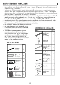
- Página 7 – INSTRUCCIONES DE INSTALACIÓN; PIEZAS INCLUIDAS; ACCESORIOS DE INSTALACIÓN; PARTE
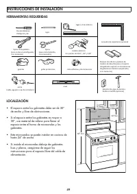
- Página 8 – • El espacio entre los gabinetes debe ser de 30”
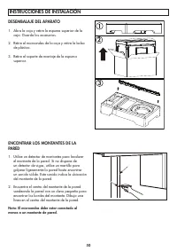
- Página 9 – DESEMBALAJE DEL APARATO; Abra la caja y retire la espuma superior de la
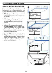
- Página 10 – USO DE LA PLANTILLA DE INSTALACIÓN; La parte superior de; Gabinete inferior empotrado enmarcado; La parte superior de la; Alineación de la línea central de la plantilla; Mida el espacio donde
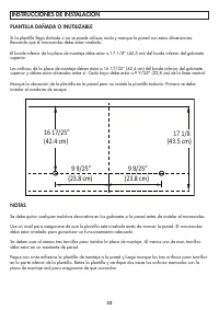
- Página 11 – PLANTILLA DAÑADA O INUTILIZABLE
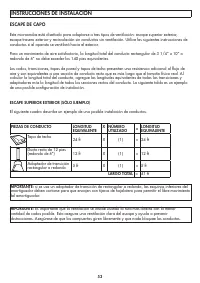
- Página 12 – ESCAPE DE CAPO; Tapa de techo
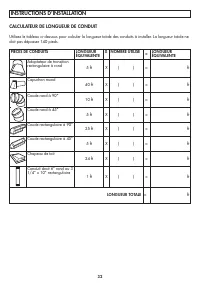
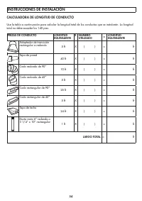
- Página 13 – CALCULADORA DE LONGITUD DE CONDUCTO
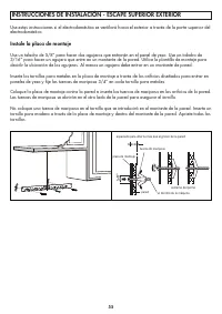
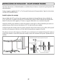
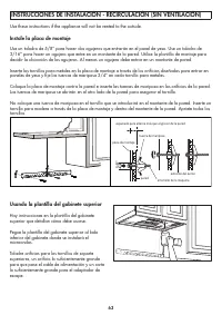
- Página 14 – Instale la placa de montaje; INSTRUCCIONES DE INSTALACIÓN - ESCAPE SUPERIOR EXTERIOR
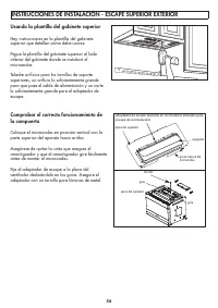
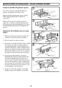
- Página 15 – Usando la plantilla del gabinete superior
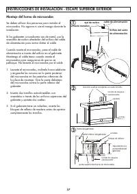
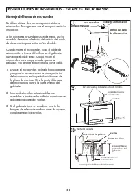
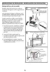
- Página 16 – Montaje del horno de microondas; Levante el microondas, inclínelo hacia adelante; ojal de nailon
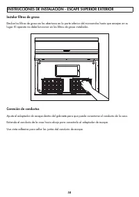
- Página 17 – Instalar fi ltros de grasa; Use cinta adhesiva para sellar las juntas del conducto de escape.
- Página 18 – INSTRUCCIONES DE INSTALACIÓN - ESCAPE EXTERIOR TRASERO
- Página 21 – INSTRUCCIONES DE INSTALACIÓN - RECIRCULACIÓN (SIN VENTILACIÓN)
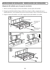
- Página 22 – Adaptación del ventilador para el escape de recirculación
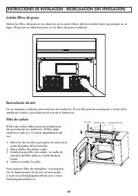
- Página 24 – Filtro de carbón; Retire los dos tornillos que sujetan la rejilla en la; Recirculación de aire
INSTRUCTIONS D’INSTALLATION
At least 24
.&87287)25+25,=217$/
2876,'((;+$867
72('*(
5($5:$//7(03/$7(
0,1,080:,'7+5(48,5('
&$87,21,)(;+$867$'$3725,6326,7,21('2876,'(
&87+2/(7+528*+5($5:$//)25(;+$867$'$3725
5(&200(1'('',0(16,21ˈ*5($6(/$'(1$,5:,//
',6&+$5*(,172+286(6758&785(
IN THE INSTALLATION INSTRUCTI
O
N
N
S
S
N
REA
OT
D
E
:I
A
T
N
I
D
S
F
V
O
E
L
R
L
Y
O
IM
W
P
T
O
H
R
E
T
D
A
I
N
RE
T
C
T
T
O
IO
BEFORE PROCEEDING WITH THIS
REAR WALL TEMPLATE.
let.
This Rear Wall Template serves to position the bottom
ut
1
a
m
.
cc
o
Us
u
e
r
a
unting
a
t
el
lev
y
p
.
el
late
to
an
che
d t
c
o
k
th
loc
a
a
t
te
the
th
e
te
h
m
o
p
riz
late
o
i
ntal
s
p
e
osi
xha
tion
ust
e
d
o
o
2
f
.
Locate and mark at least one stud on the left or right side
the centerline.
IMPROTANT:
m
Loc
o
ate
unting
an
d
p
m
late
a
.
rk holes to align with holes in the
THE CENTERLINE.
LOCATE AT LEAST ONE STUD ON EITHER SIDE OF
MARK THE LOCATION FOR 2 ADDITIONAL, EVENLY
SP
AR
A
EA.
CED TOGGLE BOLTS IN THE MOUNTING PLATE
A
C
B
Trim the rear wall template along the dotted line.
6"
1
.&87287)25+25,=217$/
2876,'((;+$867
72('*(
5($5:$//7(03/$7(
0,1,080:,'7+5(48,5('
&$87,21,)(;+$867$'$3725,6326,7,21('2876,'(
5(&200(1'('',0(16,21ˈ*5($6(/$'(1$,5:,//
&87+2/(7+528*+5($5:$//)25(;+$867$'$3725
',6&+$5*(,172+286(6758&785(
N
REA
OT
D
E
:I
A
T
N
I
D
S
F
V
O
E
L
R
L
Y
O
IM
W
P
T
O
H
R
E
T
D
A
I
N
RE
T
C
T
T
O
IO
IN THE INSTALLATION INSTRUCTI
O
N
N
S
S
BEFORE PROCEEDING WITH THIS
REAR WALL TEMPLATE.
let.
This Rear Wall Template serves to position the bottom
ut
1
a
m
.
cc
U
o
s
u
e
r
a
unting
a
t
el
lev
y
p
.
el
late
to
an
che
d t
c
o
k
th
loc
a
a
t
te
the
th
e
te
h
m
o
p
riz
late
o
i
ntal
s p
e
osi
xha
tion
ust
e
d
o
o
2
f
.
Lo
the
c
a
c
t
e
e a
nter
nd
li
m
ne
a
.
rk at least one stud on the left or right side
IMPROTANT:
m
Loc
o
ate
unting
an
d
p
m
late
a
.
rk holes to align with holes in the
THE CENTERLINE.
LOCATE AT LEAST ONE STUD ON EITHER SIDE OF
MARK THE LOCATION FOR 2 ADDITIONAL, EVENLY
SP
AR
A
EA.
CED TOGGLE BOLTS IN THE MOUNTING PLATE
A
C
B
Trim the rear wall template along the dotted line.
6"
2
.&87287)25+25,=217$/
2876,'((;+$867
72('*(
5($5:$//7(03/$7(
0,1,080:,'7+5(48,5('
&$87,21,)(;+$867$'$3725,6326,7,21('2876,'(
5(&200(1'('',0(16,21ˈ*5($6(/$'(1$,5:,//
&87+2/(7+528*+5($5:$//)25(;+$867$'$3725
',6&+$5*(,172+286(6758&785(
N
REA
OT
D
E
:I
A
T
N
I
D
S
F
V
O
E
L
R
L
Y
O
IM
W
P
T
O
H
R
E
T
D
A
I
N
RE
T
C
T
T
O
IO
IN THE INSTALLATION INSTRUCTI
O
N
N
S
S
BEFORE PROCEEDING WITH THIS
REAR WALL TEMPLATE.
let.
This Rear Wall Template serves to position the bottom
ut
1
a
m
.
cc
o
Us
u
e
r
a
unting
a
t
el
lev
y
p
.
el
late
to
an
che
d t
c
o
k
th
loc
a
a
t
te
the
th
e
te
h
m
o
p
riz
late
o
i
ntal
s p
e
osi
xha
tion
ust
e
d
o
o
2
f
.
Locate and mark at least one stud on the left or right side
the centerline.
IMPROTANT:
m
Loc
o
ate
unting
an
d
p
m
late
a
.
rk holes to align with holes in the
THE CENTERLINE.
LOCATE AT LEAST ONE STUD ON EITHER SIDE OF
MARK THE LOCATION FOR 2 ADDITIONAL, EVENLY
SP
AR
A
EA.
CED TOGGLE BOLTS IN THE MOUNTING PLATE
A
C
B
Trim the rear wall template along the dotted line.
6"
3
.&87287)25+25,=217$/
2876,'((;+$867
72('*(
5(&200(1'('',0(16,21ˈ*5($6(/$'(1$,5:,//
',6&+$5*(,172+286(6758&785(
5($5:$//7(03/$7(
&$87,21,)(;+$867$'$3725,6326,7,21('2876,'(
&87+2/(7+528*+5($5:$//)25(;+$867$'$3725
N
RE
O
A
T
D
E
:I
A
T
N
I
D
S
F
V
O
E
L
R
L
Y
O
IM
W
P
T
O
H
R
E
T
D
A
I
N
RE
T
C
T
T
O
IO
IN THE INSTALLATION INSTRUCTI
O
N
N
S
S
BEFORE PROCEEDING WITH THIS
REAR WALL TEMPLATE.
let.
This Rear Wall Template serves to position the bottom
ut
1
a
m
.
cc
U
o
s
u
e
r
a
unting
a
t
el
lev
y.
plat
el
e
to
an
che
d t
c
o
k
th
loc
a
a
t
te
the
th
e
te
h
m
o
p
riz
late
o
i
ntal
s p
e
osi
xha
tion
ust
e
d
o
o
2
f
.
Lo
the
c
a
c
t
e
e a
nter
nd
li
m
ne
a
.
rk at least one stud on the left or right side
IMPROTANT:
m
Loc
o
ate
unting
an
d
plat
m
e
a
.
rk holes to align with holes in the
THE CENTERLINE.
LOCATE AT LEAST ONE STUD ON EITHER SIDE OF
MARK THE LOCATION FOR 2 ADDITIONAL, EVENLY
SP
ARE
A
A.
CED TOGGLE BOLTS IN THE MOUNTING PLATE
A
B
Trim the rear wall template along the dotted line.
0,1,080:,'7+5(48,5('
C
6"
4
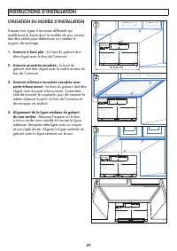
UTILISATION DU MODÈLE D’INSTALLATION
Il existe trois types d’armoires différents qui
modifi eront la façon dont le modèle de mur arrière
doit être utilisé pour déterminer où installer le
support de montage.
1. Armoire à fond plat :
Le haut du gabarit doit
être aligné avec le bas de l’armoire.
2. Armoire encastrée encadrée :
le haut du
gabarit doit être aligné avec le cadre arrière du
bas de l’armoire.
3. Armoire inférieure encastrée encadrée avec
porte-à-faux avant :
Le haut du gabarit doit être
aligné avec le porte-à-faux avant. Il peut être
utile de mesurer le surplomb, puis de mesurer la
même distance à partir du bas de l’armoire et
de marquer cet endroit.
4. Alignement de la ligne médiane du gabarit
du mur arrière :
Mesurez l’espace où le four
à micro-ondes sera installé et trouvez la ligne
médiane. Marquez cette ligne avec un crayon
et une règle droite. Alignez la ligne centrale du
gabarit avec la ligne centrale sur le mur.
29
"Cargando la instrucción" significa que debes esperar hasta que el archivo se cargue y puedas leerlo en línea. Algunas instrucciones son muy grandes y el tiempo de carga depende de la velocidad de tu conexión a Internet.
Resumen
¡GUARDA ESTAS INSTRUCCIONES! INSTRUCCIONES DE PUESTA A TIERRA Este aparato debe estar conectado a tierra. En caso de un cortocircuito eléctrico, la conexión a tierra reduce el riesgo de descarga eléctrica al proporcionar un cable de escape para la corriente eléctrica. Este electrodoméstico está equi...
¡GUARDA ESTAS INSTRUCCIONES! LAS INSTRUCCIONES DE SEGURIDAD • Asegúrese de que las piezas de los componentes se reemplacen con componentes similares y que el servicio lo realice personal de servicio autorizado de fábrica, para minimizar el riesgo de una posible ignición debido a piezas incorrectas o...
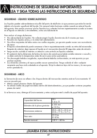
INSTRUCCIONES DE SEGURIDAD IMPORTANTESLEA Y SIGA TODAS LAS INSTRUCCIONES DE SEGURIDAD SEGURIDAD - LÍQUIDO SOBRECALENTADO Los líquidos pueden sobrecalentarse más allá del punto de ebullición sin que parezca que están hirviendo debido a la tensión superfi cial del líquido. No siempre habrá burbujas vis...
Otros modelos de microondas Danby
-
 Danby DBMW0720BWW
-
 Danby DBMW0721BBS
-
 Danby DBMW0924BBS
-
 Danby DDMW007501G1
-
 Danby DDMW01440BG1
-
 Danby DDMW01440WG1
-
 Danby DDMW1061BSS-6
-
 Danby DDMW1125BBS