GIGABYTE X299 UD4 Pro Placa base – Manual de instrucciones en formato pdf, léalo en línea gratis. Esperamos que le ayude a resolver cualquier duda que pueda tener al utilizar el aparato.
Si aún tiene preguntas, escríbalas debajo del manual de instrucciones.
"Estamos cargando el manual" significa que debe esperar a que se cargue el archivo para poder leerlo en línea. Algunos manuales son muy pesados y el tiempo que tardan en aparecer depende de su velocidad de internet.

- 1 -
English
Step
1
Installing a CPU and CPU Cooler
A. Installing an Intel CPU (skip this step if the motherboard has a built-in CPU)
•
The sequence of installation may differ depending on the type of case and devices used. The
installation instructions below apply to GIGABYTE's desktop systems and are for reference
only.
•
Refer to the user's manual included for detailed motherboard specifications.
•
Before installing the devices, make sure they are compliant with the connectors on your computer.
•
Before installing the devices, be sure to turn off the devices and your computer. Unplug the power cord
from the power outlet to prevent damage to the devices and the system components.
•
Place the computer system on a stable surface to prevent improper installation resulted from shaking.
•
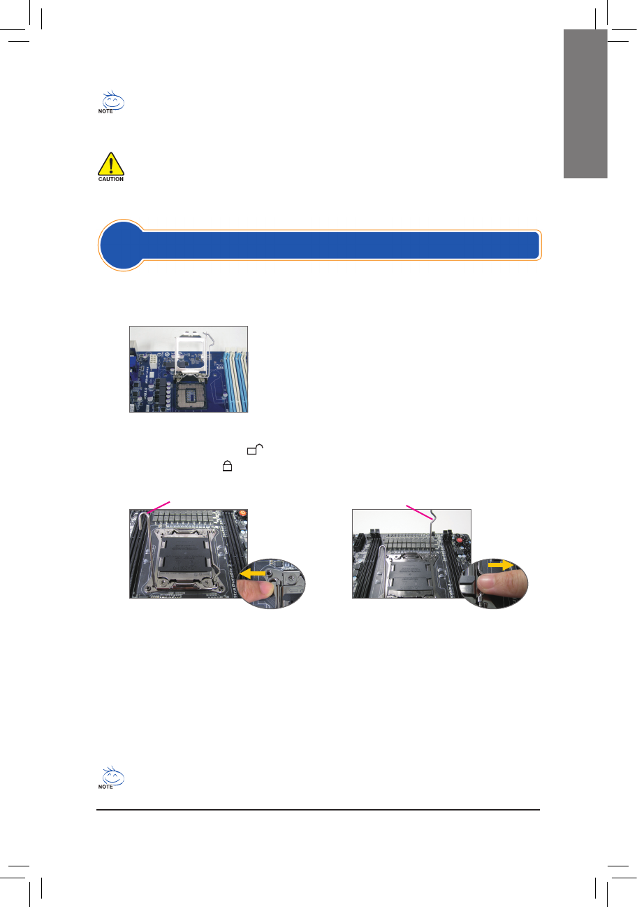
Type B:
Push lever A (closest to the "
" marking) down and away from the socket to release it. Then push
lever B (closest to the " " marking) down and away from the socket and lift it. Gently press lever A to
allow the load plate to rise. Open the load plate.
A-1 Refer to the following instructions based on your CPU specifications:
•
Type A:
Lift the CPU socket lever and the metal load plate will be lifted as well.
a. If the protective socket cover is fastened on the CPU socket, remove
it first.
b. If the protective socket cover is fastened on the metal load plate, do
not remove it at this stage. The socket cover may pop off from the
load plate automatically during the process of re-engaging the lever
after you insert the CPU.
For detailed instructions on installing the CPU, please refer to the user’s manual.
Lever A
Lever B
A-2 Hold the CPU with your thumb and index fingers. Align the CPU pin one marking (triangle) with the pin
one corner of the CPU socket (or you may align the CPU notches with the socket alignment keys) and
gently insert the CPU into position.
A-3 Once the CPU is properly inserted, replace the load plate and push the CPU socket lever back into its locked position.
Once the type B is properly inserted, carefully replace the load plate. Then secure lever B under its retention
tab. The socket cover may pop off from the load plate during the process of engaging the lever. Finally,
secure lever A under its retention tab to complete the installation of the CPU.
¿Tiene más preguntas?¿No ha encontrado la solución a su problema en el manual o tiene otros problemas? Haga su pregunta en el siguiente formulario con una descripción detallada de su situación para que otras personas y expertos puedan responderla. Si sabe cómo resolver el problema de otra persona, ayúdele :)


