Impreso en China; Inspección del funcionamiento; Retire todos los materiales de embalaje del horno de microondas. - Sharp SMO1759JS - Manual de uso - Página 27


Índice:
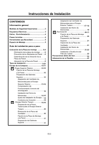
- Página 4 – CONTENIDOS; Información general; Colocación de la Placa de montaje; Instrucciones de Instalación
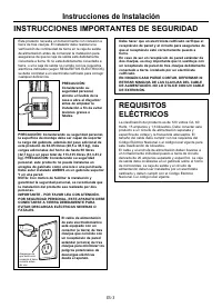
- Página 5 – REQUISITOS
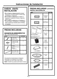
- Página 6 – Tornillos para; Si la unidad es dañada durante el envío,; INSTALACIÓN; PAQUETE DE HERRAMIENTAS; PIEZAS INCLUIDAS; PIEZAS ADICIONALES
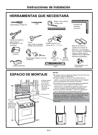
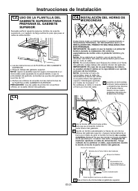
- Página 7 – ESPACIO DE MONTAJE
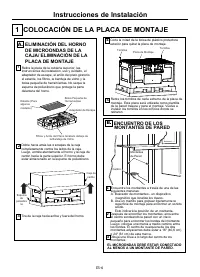
- Página 8 – EL MICROONDAS DEBE ESTAR CONECTADO; ELIMINACIÓN DEL HORNO; COLOCACIÓN DE LA PLACA DE MONTAJE; ENCUENTRO DE LOS
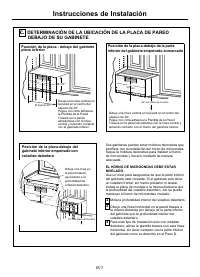
- Página 9 – EL HORNO DE MICROONDAS DEBE ESTAR
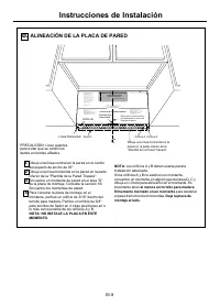
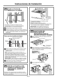
- Página 10 – NOTA: NO INSTALE LA PLACA EN ESTE; al menos un tornillo para madera; ALINEACIÓN DE LA PLACA DE PARED
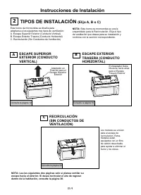
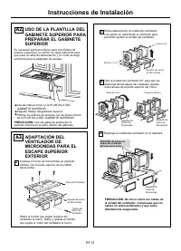
- Página 11 – TIPOS DE INSTALACIÓN; ESCAPE SUPERIOR; Consulte la página 12; NOTA: Lea las siguientes dos páginas solo si planea ventilar su
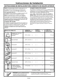
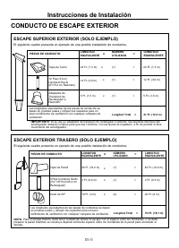
- Página 12 – no debe exceder los 120; Longitud máxima del conducto:; no; Los codos, transiciones, tapas de paredes y; INSTRUCCIONES DE INSTALACIÓN PARA CONDUCTO DE ESCAPE EXTERIOR
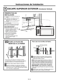
- Página 14 – Para usar los tornillos de fiador:; ESCAPE SUPERIOR EXTERIOR; Conducto Vertical
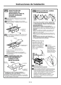
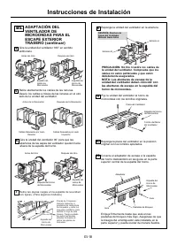
- Página 15 – ADAPTACIÓN DEL; PRECAUCIÓN: No tire ni estire los cables de
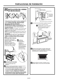
- Página 16 – INSTALACIÓN DEL PRODUCTO SEA REALIZADA
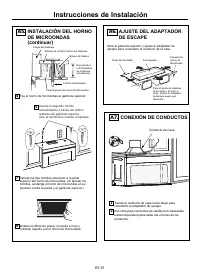
- Página 17 – AJUSTE DEL ADAPTADOR; Inserte el segundo tornillo
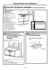
- Página 18 – ESCAPE EXTERIOR TRASERA; Conducto Horizontal
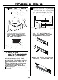
- Página 20 – NOTA: Las aberturas de escape de la
- Página 21 – INSTALACIÓN DEL HORNO; dos vueltas completas
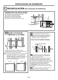
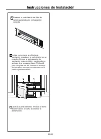
- Página 22 – PERSPECTIVA DE INSTALACIÓN; FIJAR LA PLACA DE; RECIRCULACIÓN; Sin Conductos de Ventilación
- Página 25 – Cierre la puerta del horno. Enchufe el horno
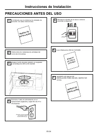
- Página 26 – PRECAUCIONES ANTES DEL USO
- Página 27 – Impreso en China; Inspección del funcionamiento; Retire todos los materiales de embalaje del horno de microondas.
Impreso en China
E
S
-25
Inspección del funcionamiento
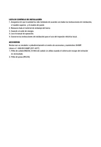
1. Compruebe que la unidad se ha instalado de acuerdo con estas instrucciones.
2. Retire todos los materiales de embalaje del horno de microondas.
3. Recupere el fusible de la casa o vuelva a encender el disyuntor.
4. Enchufe el cable de alimentación en el receptáculo.
5. Lea las instrucciones de operación antes de probar el producto.
6. Encienda el extractor de aire a alta velocidad y confirme que está funcionando con un pañuelo de papel (será adherido al
filtro).
7. Para instalaciones con ventilación exterior, confirme que se ha abierto la aleta de escape exterior.
8. Establezca el horno de microondas durante 1 minuto y confirme que el horno está funcionando normalmente usando una
taza de agua.
9. Guarde las instrucciones de instalación para uso del inspector eléctrico local.
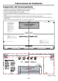
Instrucciones de Instalación
3/8" TO EDGE
NOTE: IT IS VERY IMPORTANT TO
READ AND FOLLOW THE DIRECTIONS
IN THE INSTALLATION INSTRUCTIONS
BEFORE PROCEEDING WITH THIS
REAR WALL TEMPLATE.
This Rear Wall Template serves to position the bottom
mounting plate and to locate the horizontal exhaust
outlet.
1. Use a level to check that the template is positioned
accurately.
2. Locate and mark at least one stud on the left or
right side of the centerline.
It is important to use at least one wood
screw mounted firmly in a stud to support the weight
of the microwave. Mark two additional, evenly spaced
locations for the supplied toggle bolts.
3. Drill holes in the marked locations. Where there is
a stud, drill a 3/16" hole for wood screws. For holes
that do not line up with a stud, drill 5/8" holes for
toggle bolts.
DO NOT INSTALL THE MOUNTING PLATE
AT THIS TIME.
4. Remove the template from the rear wall.
5. Review the Installation Instruction book for your
installation situation.
Locate and mark holes to align with holes in the
mounting plate.
IMPORTANT:
LOCATE AT LEAST ONE STUD ON EITHER SIDE OF
THE CENTERLINE.
MARK THE LOCATION FOR 2 ADDITIONAL, EVENLY
SPACED TOGGLE BOLTS IN THE MOUNTING PLATE
AREA.
Locate and mark holes to align with holes in the
mounting plate.
IMPORTANT:
LOCATE AT LEAST ONE STUD ON EITHER SIDE OF
THE CENTERLINE.
MARK THE LOCATION FOR 2 ADDITIONAL, EVENLY
SPACED TOGGLE BOLTS IN THE MOUNTING PLATE
AREA.
Trim the rear wall template along the dotted line.
Trim the rear wall template along the dotted line.
12"
4"
Darle vuelta a la hoja para consultar la
versión en Español.
PN:261800308463
Part No.:77222
316902476
PN:16170000A75584
3/8" TO EDGE
NOTE: IT IS
VERY IMPORT
A
NT TO
READ AND FO
LLOW THE DIRE
CTIONS
IN THE I NSTALL
ATION INSTRUC
TIONS
BEFORE PR
OC
EEDING WITH T
HIS
REAR WALL TEM
PLA
TE.
This R ear Wal l
Templat e ser ves
t o posi tio n the
bottom
mounti ng pl at e a
nd t o l ocate t
he hori zontal e
xh aust
out l et .
1. Use a l evel
to c heck t hat the
t emplat e is p
ositi oned
accur at ely
.
2. Loca t e and m
ar k at le ast o
ne s t ud on the l
eft o r
ri ght sid
e of t he c enter
line .
I t is impor tant
t o use a t l ea
st one wood
scr ew mount ed fi
rm l y in a st ud
to sup port the
weigh t
of t he mi crowa
ve. Mark two ad
diti onal , even
l y s paced
lo cat ions for
t he s uppli ed to
ggl e bol ts.
3. Dril l holes
i n t he mar ked
lo cat i ons. Wh
ere ther e is
a stu d, dr
ill a 3/1 6" hole
f or wood screw
s. For hole s
t hat do no
t l in e up with
a s t ud, d r i l l 5
/ 8" hole s fo r
t oggl e bol t
s.
DO NOT IN STALL
THE MOUNTI NG P
LATE
AT THIS TI ME.
4. Remove the t
emplat e f r om th
e r ear wall .
5. Review the I
nst allat io n I ns
t ru ctio n book fo
r you r
in stallat
i on si t uati on.
Locate an d m
ar k holes to
a l ig n wi th hol
es in the
mount ing pla
te .
IMPORTANT
:
LOCATE AT LEA
ST ONE STUD O
N EITHER SIDE
OF
THE CENTERLIN
E.
MARK THE LOCA
TION FOR 2 AD
DITIONAL, EVE
NLY
SPACE
D TOGGLE B
OLTS IN THE M
OU
NTING PLATE
AREA.
Locat e and m
ar k h ole s t o
a lig n with hol
es in the
mount ing pla
te.
IMPORTANT
:
LOCATE AT LEAS
T ONE STUD O
N EITHER SIDE
OF
THE CENTERLINE
.
MARK THE LOCA
TION FOR 2 ADD
ITIONAL, EVEN
LY
SPACED TOGG
L
E BOLTS IN TH
E MOUNTING PL
AT
E
AREA.
Trim the rea
r wal l templ at
e a long th e d
ott ed line .
Trim the rear
wall t emplat
e al ong th e do
tt ed l in e.
12"
4"
Darle vuelta a l a
hoj a par a consu
lta r l a
versi ón en Esp
añol .
3/ 8" TO EDGE
NOTE: IT IS V
ERY IMPORTAN
T TO
READ AND FO
LLOW
THE DIRECTIO
NS
IN T HE INST
ALLATION IN
STRUCTIO
NS
BEFORE P
RO
CEEDING WITH
THIS
REAR WALL TEMPL
ATE.
This Rear Wall
Templ at e ser
ves to posi t i
on the b ot tom
mount i ng pl ate
and t o locat
e t he h orizon
t al exhaust
outlet .
1. Use a lev el
t o c heck t ha
t t he templ at
e i s posit i on
ed
acc ur at el
y.
2. Locat e and
mar k at lea
st o ne s t ud o
n t he l eft or
rig ht si d
e of t he cent
erl i ne.
I t i s i mpor t an
t t o use a t l
east one wood
screw mount ed
fi r mly i n a
stu d t o supp
ort the wei gh
t
of the micr owa
ve. Mar k t wo
addi t io nal, eve
nly spaced
l ocat i ons f or
t he s uppli ed
to ggle bo lt s.
3. Dr i l l hol e
s i n t he mar k
ed l ocat i ons.
Wher e th ere i
s
a s t ud, d
r i l l a 3/ 16"
hol e for wood
screws. For h
ole s
tha t do n
ot l i ne up wi
t h a stu d, d r
i ll 5/8 " hol e
s fo r
tog gl e bo
l t s.
DO NOT INSTALL
THE MOUNTI NG
PLATE
AT T HIS TI ME
.
4. Remove the
t emplate f r om
the r ear wall
.
5. Rev i ew t he
In sta l l ation
In str uct i on
book f or your
ins t al l at
i on si t uati on
.
Locat e and m
ark holes to
al ig n with h
o les in th
e
mounting pla
t e.
IMPORTAN
T:
LOCATE AT LEAS
T ONE STUD O
N E I THER SI
D
E OF
THE CEN
TERLI NE.
MARK TH
E LOCATI ON FO
R 2 ADDITIO
N
AL, EVEN
L
Y
SPACED TOG
GLE BO
LTS I N THE
MOUNT
ING PLATE
AREA.
Locat e and ma
rk holes to
al ig n with h
o les in th
e
mounting pla
t e.
IMPORTAN
T:
LOCAT
E AT LEAST
ONE STUD ON
E I THER SI
D
E OF
THE CENTER
LINE.
MARK THE L
OCATIO
N FOR 2 ADD
ITION
AL, EVEN
L
Y
SPACED TO
GGLE
BOLTS IN
T HE MOUN
TING
PLATE
AREA.
Trim t he rear
wa ll templ
ate a l ong t
he dotted l i
ne.
Trim the r ea
r wall templa
te al ong the dot
ted l i ne.
12"
4"
Darle vuelta a
la hoja para co
nsultar la
versión en Es
pañol.
A06823428
"Cargando la instrucción" significa que debes esperar hasta que el archivo se cargue y puedas leerlo en línea. Algunas instrucciones son muy grandes y el tiempo de carga depende de la velocidad de tu conexión a Internet.
Resumen
Adaptación del Ventilador de Microondas para el Escape Exterior Trasero ......................... Instalación del Horno de Microondas ..................................... Recirculación .................................... Fijación de la Placa de Montaje a la Pared ..............................
Este producto necesita un tomacorriente con conexión a tierra de tres clavijas. El instalador debe realizar una verificación de continuidad de tierra en la caja de salida de alimentación antes de comenzar la instalación para asegurarse de que la caja de salida esté debidamente conectada a tierra. Si...
PIEZA CANTIDAD Tornillos para Madera ( 1 / 4 "×2") 2 Tornillos de Fiador (y tuercas de alas) ( 3 / 16 "×3") 3 Tornillos Autoalineadores para Máquina ( 1 / 4 "-28×3 1 / 4 ") Ojal de Nylón (para gabinetes de metal) 1 • Si la unidad es dañada durante el envío, devuélvalo a la ti...