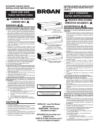
INSTALL RANGE HOOD - Broan-NuTone 413023 - Manual de uso - Página 4
Índice:
- Página 3 – PREPARE THE HOOD
- Página 4 – INSTALL RANGE HOOD
- Página 5 – USE AND CARE
*
*
Duct cutouts
not centered on
21” hood width.
4
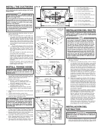
INSTALL RANGE HOOD
WARNING
TURN OFF THE PROPER CIRCUIT AT THE
SERVICE ENTRANCE BEFORE WIRING THIS
RANGE HOOD.
1. Run electric wiring through hole drilled in wall or
cabinet. Split wiring for 6” and install proper con-
nector for type of wire used. (FIG. 9)
2. Position hood so that:
a.) Wiring is routed through knockout
opening (FIG. 10) (MX Series Only: Use
grommet supplied in parts bag.)
b.) Large part of keyhole slots fit over hood
mounting screws. (FIG. 10)
c.) Damper/duct connector slides into duct
work. (40000, 42000 and 42000D hoods
only)
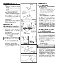
3. Adjust hood so that hood front is flush with cabinet
frame.
4. Tighten hood mounting screws firmly.
5. Fasten wiring to hood with proper electrical con-
nector for type of wire being used.
WARNING
A L L E L E C T R I CA L C O N N E C T I O N S M U ST
BE IN ACCORDANCE WITH LOCAL CODES,
ORDINANCES, OR NATIONAL ELECTRICAL
CODE. IF YOU ARE UNFAMILIAR WITH METH-
ODS OF INSTALLING ELECTRICAL WIRING,
SECURE THE SERVICES OF A QUALIFIED
ELECTRICIAN.
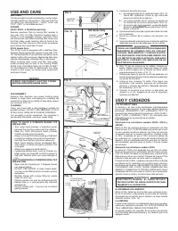
6. Strip 1/2” of insulation from wires. Connect white
to white, black to black, and green to prepared
hole with green ground screw provided. (FIG. 11)
7. Replace wiring box cover and screw. Make sure
that all wiring is safely contained inside.
8. Install light (75 Watt maximum). For easier instal-
lation, squeeze plastic lens and remove it from
hood. Remember to reinstall lens. (FIG.12)
9. Turn on power and check operation of fan and
light. Make sure that damper operates freely.
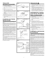
INSTALL THE DUCTWORK
(This section for 40000 and 42000 hoods only.
41000 hoods skip this section and go on to “Install
Range Hood”.)
NOTE
These instructions will follow plans made on
Page 2. Start at the exterior and run ductwork
back to the range hood.
For best possible performance, use the short-
est possible duct run and a minimum number of
elbows. Do not vent a range hood into an attic
space. A buildup of grease in the attic could
become a fire hazard.
Use only metal ductwork. DO NOT USE PLAS-
TIC DUCT. Assemble duct run securely so that
in case of a grease fire on the range, the fire will
be contained inside metal ductwork.
Tape all duct connections.
1. Follow appropriate directions below for type of
duct run you install.
a.) Wall Cap Discharge; (FIG. 7) Use saber saw
or keyhole saw to cut hole slightly larger than
duct size used so that duct will line up easily
with damper/duct conector on hood. Install
casing strips if cap will be installed on siding.
Attach required amount of duct to wall cap and
run duct back to hood. Fasten cap to wall and
caulk well.
b.)
Roof Cap Discharge; (FIG. 8) Cut a hole in
roof slightly larger than duct size being used.
Run ductwork down to hood location. Leave
3/4” of duct projecting above roof surface on
high side.
Trim duct parallel to roof pitch and seal all
around duct with roof cement.
Carefully trim shingles and slide back of roof
sheet under shingles. Nail roof sheet to roof
under shingles at top two corners and two
sides. Nail sheet directly to roof in four places
at bottom.
Using roof cement, seal all nail heads and
shingles which were cut or lifted. Do not seal
bottom edge of roof sheet.
KEYHOLE SLOT OUTLINE
CONTORNO DE LA RANURA
FILLER STRIPS
PIEZAS DE MADERA
ROOF CAP
CASQUETE DE TECHO
DUCT
DUCTO
SOFFIT
PLAFON
CABINET
GABINETE
FIG. 6
FIG. 7
CABINET
GABINETE
FIG. 8
CENTER
LINE
LINEA DE
CENTROS
SOFFIT
PLAFON
WALL CAP
CASQUETE
DE PARED
3/4”
3/4PLG.
INSTALACION DEL DUCTO
(Esta sección es solamente para los extractores
modelos 40000 y 42000. Los modelos 41000 pueden
saltarse ésta sección y continuar en la “INSTALACION
DEL EXTRACTOR”.)
NOTA
Estas instrucciones seguirán los planes descritos
en la pág 2. Comience a trabajar del exterior al
interior para conectar el ducto con el extractor.
Para obtener un mejor funcionamiento del extrac-
tor, procure que la salida del ducto sea la más
directa y que tenga el menor número de codos.
No permita que la salida del extractor quede en
un desván. Si se forma una capa de grasa en el
desván puede ser peligroso y causar un incendio.
Utilice solamente ductos de metal. NO USE DUC-
TOS DE PLASTICO. Ensamble el ducto firmemente
para que en caso de que se prenda debido a la
grasa, el fuego se contenga dentro del ducto de
metal. Coloque cinta de aislar en todas las con-
exiones del ducto.
1. Siga las incicaciones adecuadas para el tipo de ducto
que vaya a instalar.
a.) Salida del casquete de pared: (FIG.7) Utilice
un serrucho o una sierra de calador para cortar
un orificio un poco más grande que el tamaño
del ducto, para poder acomodar facilmente el
ducto con el conector del ducto/regulador en el
extractor. Si el casquete se va a instalar en un
lado, instale las tiras del marco. Fije la cantidad
requerida del ducto en el casquete de pared y
a c o m o d e e l d u c t o e n e l e x t r a c t o r . A j u s t e e l
casquete a la pared. Fijelo con un martillo. (Si la
pared es de concreto u otro material, ejecute las
operaciones necesarias para obtener los mismos
resultados.)
b.) Salida del casquete por el techo: (FIG. 8) Haga un
orificio en el techo, ligeramente más grande que
la circunferencia del ducto que se está usando.
Coloque el ducto debajo del lugar donde va el
extractor. Deje que 3/4 plg. del ducto sobresalgan
por encima de la superficie en el lado alto del techo.
Ajuste el ducto paralelamente con la inclinación
del techo y selle alrededor del tubo con cemento
para techos o tejados.
Empareje las tejas con cuidado y deslice la placa
del tejado que está debajo de las tejas. Clave la
placa del tejado a la parte de techo que está
bajo las tejas en las dos esquinas y los dos
lados superiores. Clave la placa directamente
al tejado en cuatro extremos en la parte inferior.
Utilizando cemento para tejado, selle todas las
cabezas de los clavos y las tejas que fueron
cortadas o levantadas. No selle el extremo
inferior de la placa del tejado. (Si el techo es
de concreto haga las operaciones necesarias
para obtener los mismos resultados.)
INSTALACION DEL
EXTRACTOR
ADVERTENCIA
DESCONECTE EL CIRCUITO EN LA ENTRADA DE
SERVICIO ANTES DE CONECTAR EL CABLEADO
DEL EXTRACTOR.
1. Pase el cableado eléctrico a través de un orificio en la
pared o el gabinete. Separe el cableado a 6 plg. e instale
el conector apropiado para el tipo de cable usado. (FIG. 9)
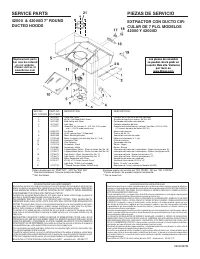
A = 7-15-16” FOR 21” RANGE HOODS
A = 7-15-16 PLG. PARA EXTRACTORS DE 21 PLG.
B = 10-15-16” FOR 21” RANGE HOODS
B = 10-15-16 PLG. PARA EXTRACTORS DE 21 PLG.
A & B = 10-15/16” FOR 24” RANGE HOODS
A & B = 10-15/16 PLG. PARA EXTRACTORS DE 24 PLG.
A & B = 13-15/16” FOR 30” RANGE HOOD
A & B = 13-15/16 PLG. PARA EXTRACTOR DE 30 PLG.
A & B = 16-15/16” FOR 36” RANGE HOOD
A & B = 16-15/16 PLG. PARA EXTRACTOR DE 36 PLG.
A & B = 19-15/16” FOR 42” RANGE HOOD
A & B = 19-15/16 PLG. PARA EXTRACTOR DE 42 PLG.
FIG. 5B
40000 AND 41000
MODELOS 40000
Y 41000
42000
MODELO 42000
* Duct cutouts not centered on
21” hood width.
* Los recortes de los conductos
no centran el 21 pulg. de ancho
campana.
9
7
/
8
”
3
/
4
”
7
1
/
2
”
7
1
/
2
”
5
1
/
4
”
5
1
/
4
”
3
7
/
8
”
1
/
8
”
6
7
/
8
”
10
5
/
8
”
10
1
/
2
”
1
1
/
2
”
12”
CENTER LINE
LINEA DE CENTRO
A
HOOD WIDTH / ANCHO DEL EXTRACTOR
FILLER
STRIP
PIEZA DE
MADERA
FILLER
STRIP
PIEZA DE
MADERA
B
FIG. 5A
"Cargando la instrucción" significa que debes esperar hasta que el archivo se cargue y puedas leerlo en línea. Algunas instrucciones son muy grandes y el tiempo de carga depende de la velocidad de tu conexión a Internet.
Resumen
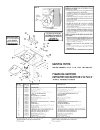
3 KEYHOLE SLOTS RANURAS DAMPER/DUCT CONNEC- TOR (40000 HOOD ONLY) CONECTOR DEL DUCTO/ REGULADOR (SOLO PARA EL MODELO 40000) HINGE PINSPASADORES DE BISAGRA DUCT KNOCKOUTS TAPONES DEL DUCTO PREPARANDO EL EXTRACTOR 1. Desempaque el extractor y revise el contenido de la caja. Usted debe encontrar: 1 - ...
* * Duct cutouts not centered on 21” hood width. 4 INSTALL RANGE HOOD WARNING TURN OFF THE PROPER CIRCUIT AT THE SERVICE ENTRANCE BEFORE WIRING THIS RANGE HOOD. 1. Run electric wiring through hole drilled in wall or cabinet. Split wiring for 6” and install proper con- nector for type of wire used. (...
CONNECTORCONECTOR 5 SOCKETENCHUFE LIGHT LENSLAMPARA FILTER RETAINERSOPORTE DEL FILTRO TABSAPENDICES FAN ASSEMBLY Remove filter. Remove t wo screws holding motor bracket to range hood, and unplug fan assembly. Be careful not to allow fan assembly to drop when screws are removed. (FIG. 14) CLEANING Cl...
Otros modelos de campanas extractoras Broan-NuTone
-
 Broan-NuTone AR130SS
-
 Broan-NuTone AVSC130SS
-
 Broan-NuTone BUEZ030WW
-
 Broan-NuTone BUEZ130WW
-
 Broan-NuTone BUEZ230WW
-
 Broan-NuTone BUEZ330WW
-
 Broan-NuTone BWS2304SS
-
 Broan-NuTone BWT2304SSB
-
 Broan-NuTone E6430SS
-
 Broan-NuTone RL6230WH