Dewalt DW235G - Manual de uso
Taladro Dewalt DW235G - Manual de uso, léela gratuitamente en línea en formato PDF. Esperamos que esto te ayude a resolver cualquier duda que puedas tener. Si tienes más preguntas, contáctanos a través del formulario de contacto.

NOTE:
Use lower speeds for starting holes without a center punch, drilling in metal or plastics,
driving screws or drilling ceramics. Higher speeds are better for drilling wood and composition
boards, and for using abrasive and polishing accessories.
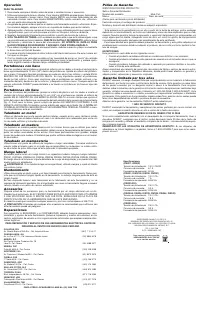
THE REVERSING LEVER
The reversing lever changes the direction of rotation of the drill and is used when backing out
screws and jammed drill bits. To operate the tool in reverse, release the trigger switch and push
the lever to the left (when viewed from the chuck end) as shown in Figure 2. To operate the drill
in forward for drilling holes or driving screws (as well as when using other accessories) release
the trigger switch and push the lever to the right (when viewed from the chuck end).
Return the reversing lever to the forward position after all operations in reverse are completed.
SWITCH LOCK-ON
Your drill is equipped with a switch lock-on feature. If you wish to disable this feature, take your
tool to any authorized service center. The service center can provide a lock-out key to prevent
the unit from being locked in the on position (Figure 3).
Operation
DRILLING
1. Always unplug the drill when attaching or changing bits or accessories.
2. Use sharp drill bits only. For WOOD, use twist drill bits, spade bits, power auger bits, or hole
saws. For METAL, use high speed steel twist drill bits or hole saws. For MASONRY, such as
brick, cement, cinder block, etc., use carbide-tipped bits.
3. Be sure the material to be drilled is anchored or clamped firmly. If drilling thin material, use a
wood “back-up” block to prevent damage to the material.
4. Always apply pressure in a straight line with the bit. Use enough pressure to keep the drill
biting, but do not push hard enough to stall the motor or deflect the bit.
5. Hold the tool firmly to control the twisting action of the drill.
6.
IF THE DRILL STALLS
, it is usually because it is being overloaded or improperly used.
RELEASE THE TRIGGER IMMEDIATELY
, remove the drill bit from work, and determine
cause of stalling.
DO NOT CLICK TRIGGER OFF AND ON IN AN ATTEMPT TO START A
STALLED DRILL — THIS CAN DAMAGE THE DRILL.
7. To minimize stalling or breaking through the material, reduce pressure on drill and ease the
bit through the last fractional part of the hole.
8. Keep the motor running when pulling the bit out of a drilled hole. This will help prevent jam-
ming.
9. With Variable Speed Drills there is no need to center punch the point to be drilled. Use a slow
speed to start the hole and accelerate by squeezing the trigger harder when the hole is deep
enough to drill without the bit skipping out.
Keyed Chucks
Open chuck jaws by turning collar with fingers and insert shank of bit about 3/4" into chuck.
Tighten chuck collar by hand. Place chuck key in each of the three holes, and tighten in
CLOCKWISE direction. It’s important to tighten chuck with all three holes to prevent slippage. To
release bit, turn chuck key COUNTERCLOCKWISE in just one hole, then loosen the chuck by
hand. Any authorized D
E
WALT service center can install a keyless chuck in place of a keyed
chuck.
Keyless Chucks
Open chuck jaws by turning plastic collar with fingers and insert shank of bit about 3/4" into
chuck. Tighten plastic collar CLOCKWISE while depressing spindle lock button on the right side
of the tool housing (Fig. 4). To release bit, turn plastic collar COUNTERCLOCKWISE while
depressing the spindle lock button (Fig. 4).
NOTE:
DO NOT DEPRESS LOCK BUTTON WHILE OPERATING DRILL or while the chuck is
moving.
Drilling in Metal
Use a cutting lubricant when drilling metals. The exceptions are cast iron and brass which should
be drilled dry. The cutting lubricants that work best are sulfurized cutting oil or lard oil; bacon-
grease will also serve the purpose.
Drilling in Wood
Holes in wood can be made with the same twist drills used for metal. These bits may overheat
unless pulled out frequently to clear chips from the flutes. For larger holes, use power drill wood
bits. Work that is apt to splinter should be backed up with a block of wood.
Drilling in Masonry
Use carbide tipped masonry bits at low speeds. Keep an even force on the drill but not so much
that you crack the brittle materials. A smooth, even flow of dust indicates the proper drilling rate.
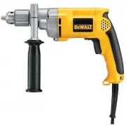
Side Handle
A side handle may be supplied with your drill. Side handles are included with these drills: DW231,
DW235G, DW235-220, DW236, DW238, DW239, DW245, DW246, DW248, DW249. The side
handle clamps to the front of the gear case and can be rotated 360 degrees to permit right or left
hand use.
CAUTION:
If a side handle is included with your drill, always use it and hold the drill with both
hands.
Maintenance
Use only mild soap and damp cloth to clean the tool. Never let any liquid get inside the tool; never
immerse any part of the tool into a liquid.
Self-lubricating bearings are used in the tool and periodic relubrication is not required. In the
unlikely event that service is ever needed, take your tool to an authorized service location.
Accessories
Recommended accessories for use with your tool are available at extra cost from your distributor
or local service center. ACCESSORY MUST BE RATED FOR USE AT SPEED EQUAL TO OR
HIGHER THAN NAMEPLATE R.P.M. OF TOOL WITH WHICH IT IS BEING USED.
If you need assistance in locating any accessory, please contact D
E
WALT Industrial Tool Co.,
701 East Joppa Road, Baltimore, MD 21286 or call 1-800-4- D
E
WALT (1-800-732-4441).
CAUTION:
The use of any non-recommended accessory may be hazardous.
Repairs
To assure product SAFETY and RELIABILITY, repairs, maintenance and adjustment (including
brush inspection and replacement) should be performed by authorized service centers or other
qualified service organizations, always using identical replacement parts.
Three Year Limited Warranty
D
E
WALT will repair, without charge, any defects due to faulty materials or workmanship for three
years from the date of purchase. This warranty does not cover part failure due to normal wear or
tool abuse. For further detail of warranty coverage and warranty repair information, visit
www.dewalt.com or call 1-800-4-D
E
WALT (1-800-433-9258). This warranty does not apply to
accessories or damage caused where repairs have been made or attempted by others. This war-
ranty gives you specific legal rights and you may have other rights which vary in certain states
or provinces.
In addition to the warranty, D
E
WALT tools are covered by our:
1 YEAR FREE SERVICE
D
E
WALT will maintain the tool and replace worn parts caused by normal use, for free, any time
during the first year after purchase.
90 DAY MONEY BACK GUARANTEE
If you are not completely satisfied with the performance of your D
E
WALT Power Tool, Laser, or
Nailer for any reason, you can return it within 90 days from the date of purchase with a receipt
for a full refund – no questions asked.
FREE WARNING LABEL REPLACEMENT:
If your warning labels become illegible or are miss-
ing, call 1-800-4-DEWALT for a free replacement.
POUR TOUT RENSEIGNEMENT SUPPLÉMENTAIRE SUR CET OUTIL OU TOUT AUTRE
OUTIL D
E
WALT, COMPOSER SANS FRAIS LE NUMÉRO :
1 800 4-D
E
WALT (1 800 433-9258)
RÈGLES DE SÉCURITÉ GÉNÉRALES
AVERTISSEMENT! Vous devez lire et comprendre toutes les instructions.
Le non-respect, même partiel, des instructions ci-après entraîne un risque de
choc électrique, d’incendie et/ou de blessures graves.
CONSERVEZ CES INSTRUCTIONS
AIRE DE TRAVAIL
•
Veillez à ce que l’aire de travail soit propre et bien éclairée
. Le désordre et le manque
de lumière favorisent les accidents.
•
N’utilisez pas d’outils électriques dans une atmosphère explosive, par exemple en
présence de liquides, de gaz ou de poussières inflammables.
Les outils électriques
créent des étincelles qui pourraient enflammer les poussières ou les vapeurs.
•
Tenez à distance les curieux, les enfants et les visiteurs pendant que vous travaillez
avec un outil électrique.
Ils pourraient vous distraire et vous faire faire une fausse
manoeuvre.
SÉCURITÉ ÉLECTRIQUE
•
Les outils mis à la terre doivent être branchés dan une prise de courant correctement
installée et mise à la terre conformément à tous les codes et règlements pertinents.
Ne modifiez jamais la fiche de quelque façon que ce soit, par exemple en enlevant la
broche de mise à la terre. N'utilisez pas d'adaptateur de fiche. Si vous n'êtes pas cer-
tain que la prise de courant est correctement mise à la terre, adressez-vous à un élec-
tricien qualifié.
En cas de défaillance ou de défectuosité électrique de l'outil, une mise à la
terre offre un trajet de faible résistance à l'électricité qui autrement risquerait de traverser l'u-
tilisateur. Les modèles DW223G et DW235G sont mis à la terre.
•
Les outils à double isolation sont équipés d’une fiche polarisée (une des lames est plus large
que l’autre), qui ne peut se brancher que d’une seule façon dans une prise polarisée Ne
modifiez pas la fiche de l’outil. Les modèles DW217, DW221, DW222, DW223, DW226,
DW231, DW235, DW236, DW245, et DW246 sont equipés d´une fishe polariseé. La double
isolation
élimine le besoin d’un cordon d’alimentation à trois fils avec mise à la terre ainsi
que d’une prise de courant mise à la terre. Les modèles DW217, DW221, DW222, DW223,
DW223-220, DW226, DW231, DW235-220, DW236, DW238, DW239 DW245,
DW246,DW248, et DW249 comportent une double isolation. Les modèles DW223-220 et
DW235-220 sont faits pour utilisés 230 volts et
•
Évitez tout contact corporel avec des surfaces mises à la terre (tuyauterie, radiateurs,
cuisinières, réfrigérateurs, etc.).
Le risque de choc électrique est plus grand si votre corps
est en contact avec la terre.
•
N’exposez pas les outils électriques à la pluie ou à l’eau.
La présence d’eau dans un
outil électrique augmente le risque de choc électrique.
•
Ne maltraitez pas le cordon. Ne transportez pas l’outil par son cordon et ne
débranchez pas la fiche en tirant sur le cordon.
N’exposez pas le cordon à la chaleur, à
des huiles, à des arêtes vives ou à des pièces en mouvement. Remplacez immédiatement
un cordon endommagé. Un cordon endommagé augmente le risque de choc électrique.
•
Lorsque vous utilisez un outil électrique à l’extérieur, employez un prolongateur pour
l’extérieur marqué «W-A» ou «W».
Ces cordons sont faits pour être utilisés à l’extérieur et
réduisent le risque de choc électrique. S’assurer que le cordon de rallonge est en bon état.
Lorsqu’on se sert d’un cordon de rallonge, s’assurer qu’il est de calibre approprié pour la ten-
sion nécessaire au fonctionnement de l’outil. L’utilisation d’un cordon de calibre inférieur
occasionne une baisse de tension entraînant une perte de puissance et la surchauffe. Le
tableau suivant indique le calibre approprié selon la longueur du cordon et les mentions de
la plaque signalétique de l’outil. En cas de doute, utiliser un cordon de calibre supérieur. Le
chiffre indiquant le calibre est inversement proportionnel au calibre du cordon.
Calibre minimal des cordons de rallonge
Tension
Longueur totale du cordon en pieds
120 V
0-25
26-50
51-100
101-150
240 V
0-50
51-100
101-200 201-300
Intensité (A)
Au Au
Calibre moyen de fil (AWG)
moins
plus
0
-
6
18
16
16
14
6
-
10
18
16
14
12
SÉCURITÉ DES PERSONNES
•
Restez alerte, concentrez-vous sur votre travail et faites preuve de jugement.
N’utilisez pas un outil électrique si vous êtes fatigué ou sous l’influence de drogues,
d’alcool ou de médicaments.
Un instant d’inattention suffit pour entraîner des blessures
graves.
•
Habillez-vous convenablement. Ne portez ni vêtements flottants ni bijoux. Confinez
les cheveux longs. N’approchez jamais les cheveux, les vêtements ou les gants des
pièces en mouvement. Des vêtements flottants, des bijoux ou des cheveux longs
risquent d’être happés par des pièces en mouvement.
Se tenir éloigné des évents
puisque ces derniers pourraient camoufler des pièces mobiles.
FIG. 1
A
FIG. 2
REVERSING LEVER
(Shown in Forward
Position)
INVERSEUR DE
MARCHE
(illustré en marche avant)
PALANCA DE REVERSA
(ilustrada en posición de
marcha hacia adelante)
FIG. 3
SWITCH ASSEMBLY
INTERRUPTEUR
MONTAJE DEL INTERRUPTOR
220 VOLT PLUG
220 BOUCHON DE VOLT
220 TAPÓN DE VOLTIO
LOCK-OUT KEY
CLÉ DE VERROUILLAGE EN
MODE D’ARRÊT
LLAVE DE SEGURIDAD
FIG. 4
SPINDLE LOCK BUTTON
BOUTON DE
VERROUILLAGE DE L’ARBRE
BOTON DEL SEGURO DE LA
FLECHA
ANTI-LOCK CONTROL INSTRUCTION LABEL
ÉTIQUETTE D'INSTRUCTION NON BLOCABLE
DE COMMANDE
ETIQUETA DE INSTRUCCION DE CONTROL DE
ANTI-CERRADURA
INDICATOR LIGHT
LE VOYANT DE
SIGNALISATION
LUZ DE INDICADOR
"Cargando la instrucción" significa que debes esperar hasta que el archivo se cargue y puedas leerlo en línea. Algunas instrucciones son muy grandes y el tiempo de carga depende de la velocidad de tu conexión a Internet.