STEP 3: HEAD ASSEMBLY - Lasko S20625 - Manual de uso - Página 2
Índice:
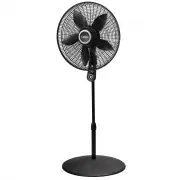
MODELO S20620
Rev. A 1/18
10
2084861
Rev. A 1/18
3
2084861
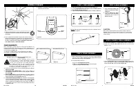
1. Take pipe assembly out of carton as shown.
(Figure 1)
2. Loosen
Height Adjustment Nut
turning counter clockwise.
(Figure 2)
3. Raise
Extension Pipe
.
(Figure 3)
4. Tighten
Height Adjustment Nut
turning clockwise.
(Figure 4)
STEP 1: PIPE ASSEMBLY
STEP 2: STAND ASSEMBLY
PLACE BASE FLAT ON FLOOR
1. With a twisting motion, insert the end of the large diameter
pipe into hole in
Base
.
(Figure 5)
Turning pipe while pushing
will assure pipe is fully seated in
Base
.
2. F o r H e i g h t A d j u s t m e n t :
a) L o o s e n
Height Adjustment Nut
.
b) Raise or lower
Extension Pipe
to desired height.
c) Tighten
Height Adjustment Nut
.
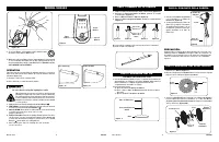
1. Place
Head Assembly
with
Collar
onto
Extension Pipe
.
(Figure 6)
2. H o l d i n g
E x t e n s i o n P i p e
firmly, twist
Head Assembly
downward until seated on
Extension Pipe
.
1. Tilt
Head Assembly
back. Put
Rear Grill
on Motor.
(Figure 7)
2 . A l i g n t a b o f P l a s t i c
Rear Grill
with groove on top of front
Motor
cover.
STEP 4: BLADE & GRILL ASSEMBLY
3. Fully seat
Rear Grill
and secure with
Plastic Nut
turning Clock-
wise. Slide
Blade
onto
Motor Shaft.
(Figure 8)
Align
Groove
on
blade hub with
Pin
on motor shaft.
(Figure 8A)
STEP 3: HEAD ASSEMBLY
Head
Assembly
Collar
Extension
Pipe
Figure 6
Figure 2
Figure 4
Figure 3
Figure 1
Height
Adjustment
Nut
Extension
Pipe
Rear
Grill
Figure 7
Motor
Rear Grill
Figure 8
Blade
Fan
Spinner
Plastic
Nut
Hacia Arriba: Estacionario
Hacia Adelante: Oscilar
Figura 10
Figura 11
Figure 5
Extension Pipe
Height
Adjustment Nut
Base
Front
Grill
FUNCIONAMIENTO
E s t e V e n t i l a d o r p u e d e h a c e r s e f u n c i o n a r m e d i a n t e l o s
Controles Manuales ubicados en la parte superior de la
unidad (como se muestra en la
Figura 9
) o con el Control Remoto
(se muestra en la
Figura 12
).
1. Conecte el cable eléctrico a un tomacorriente de 120 V~.
2. Coloque el ventilador sobre una superficie firme y nivelada.
Asegúrese que el enchufe encaje firmemente en el
tomacorriente.
C u a n d o l o s e n c h u f e s q u e d a n f l o j o s e n l o s
t o m a c o r r i e n t e s , p u e d e n d e s l i z a r s e p a r c i a l
o c o m p l e t a m e n t e f u e r a d e l t o m a c o r r i e n t e
c o n u n l e v e m o v i m i e n t o d e l c a b l e a d o s a d o .
L o s t o m a c o r r i e n t e s e n e s t e e s t a d o p o d r í a n
sobrecalentarse y representar un grave peligro de
incendio; si está cubierto por una cortina o tela,
el riesgo de incendio es aún mayor.
3. Conecte la energía eléctrica a su ventilador pulsando el
Botón
Alimentación
( ).
4.
VELOCIDAD DEL VENTILADOR:
Ahora puede ajustar la
velocidad del ventilador al nivel deseado pulsando el
Botón
Velocidad
( ).
5.
OSCILACION:
Empuje la perilla ubicada en la parte superior
de la caja del motor para hacer que la cabeza del Ventilador se
mueva de un lugar hacia otro.
(Figuras 10 y 11)
6.
FUNCIÓN DE TEMPORIZADOR: Este ventilador está equipado
con un temporizador. El temporizador puede ser programado
7 horas. Continúe oprimiendo el Botón Temporizador ( ) para
lograr el tiempo de programación deseado. Para cancelar el
temporizador, presione el botón del temporizador hasta que
se apague la luz.
Botón
Temporizador
Botón
Alimentación
Botón
Velocidad
Figura 9
CAUTION:
When making height adjustment after head assembly is attached,
ALWAYS support extension pipe with one hand, as loosening height
adjustment nut may otherwise cause rapid fall of extension pipe and
head assembly.
Do Not
take pipe apart. Should pipes become separated, insert
pipe A into pipe B.
A
B
4. Para asegurar la Helice, enroscarla hasta que quede
apretada en el Cubo de la Tapa haciéndola girar Hacia
la Izuierda.
Figura 8A
Pasador
Ranura
del Cubo
5. Con la cabeza del ventilador en posición vertical, coloque la
rejilla frontal alineando el ornamento en forma horizontal.
Asegure las rejillas insertando estas comenzando por la parte
de abajo y siguiendo hacia arriba. NO NECESITO EL GAN
CHOS DE LA REJILLA PARA ENSAMBLE.
7.
Después de apagar el Ventilador, desconecte la unidad del
tomacorriente eléctrico.
"Cargando la instrucción" significa que debes esperar hasta que el archivo se cargue y puedas leerlo en línea. Algunas instrucciones son muy grandes y el tiempo de carga depende de la velocidad de tu conexión a Internet.
Resumen
MODELO S20620 Rev. A 1/18 10 2084861 Rev. A 1/18 3 2084861 1. Take pipe assembly out of carton as shown. (Figure 1) 2. Loosen Height Adjustment Nut turning counter clockwise. (Figure 2) 3. Raise Extension Pipe . (Figure 3) 4. Tighten Height Adjustment Nut turning clockwise. (Figure 4) STEP 1: PIPE ...
Tubo de Extensión Tuerca de Ajuste de Altura Base 1. Con un movimiento rápido, inserte el extremo de la tubería de gran diámetro en el agujero en la base. ( Figura 5) En cuanto la tubería mientras se empuja asegurará la tubería esté completamente asentado en la base. 2. Para ajustar la altura: a) ...
Rev. A 1/18 8 2084861 Rev. A 1/18 5 2084861 MODEL S20620 REMOTE CONTROL 1. Install batteries (not included) as shown in Figure 12 . The battery is type “AAA”. 2. The Remote Control Power Button is labeled as ( ). 3. All the functions performed with the Remote Control work identically to the Manual ...
Otros modelos de ventiladores Lasko
-
 Lasko 1646
-
 Lasko 1823
-
 Lasko 1843
-
 Lasko 1850
-
 Lasko 2520
-
 Lasko 2521
-
 Lasko 2524
-
 Lasko 2526
-
 Lasko 2535
-
 Lasko 2551