PASO 3: CONJUNTO DE LA CABEZA - Lasko S20625 - Manual de uso - Página 3
Índice:
Tubo de Extensión
Tuerca de Ajuste de
Altura
Base
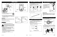
1. Con un movimiento rápido, inserte el extremo de la tubería de
gran diámetro en el agujero en la base. (
Figura 5)
En cuanto la
tubería mientras se empuja asegurará la tubería esté
completamente asentado en la base.
2. Para ajustar la altura:
a) Afloje la
Tuerca de Ajuste de Altura
.
b) Eleve o baje el
Tubo de Extensión
hasta obtener la altura
deseada.
c) Apriete la
Tuerca de Ajuste de Altura
.
MODEL S20620
Rev. A 1/18
4
2084861
Rev. A 1/18
9
2084861
1. Inclinarla
Cabeza del Ventilador
hacia atrás. Coloque la
Rejilla
Trasera
en el
Motor. (Figura 7)
2. Alinear la lengüeta de la
Rejilla Trasera
con la ranura en la parte
superior de la cubierta delantera del
Motor
.
PASO 4: ENSAMBLE DEL ASPAY REJILLA
PASO 2: ENSAMBLE DEL PIE
COLOQUE LA BASE EN EL PISO
1. Coloque el
Conjunto de Cabezal
con el
Collar
en el
Tubo de
Extensión. (Figura 6)
2. Sostenga firmemente el Tubo de
Extensión y empuje el Conjunto
de Cabezal hacia abajo con un
movimiento giratorio hasta que
quede asentado en el Tubo de
Extensión.
PASO 3: CONJUNTO DE LA CABEZA
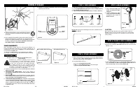
1. Saque el conjunto de la tubería del cartón como muestra.
(Figura 1)
2. Desafloje la
Tuerca de Ajuste de Altura
, girando en sentido
contrahorario.
(Figura 2)
3. Eleve la
Extensión De La Tubería.
(Figura 3)
4. Apriete la
Tuerca de Ajuste de Altura
, girando en sentido horario.
(Figura 4)
PASO 1: ARMADO DE LA TUBERÍA
3. Asiente la
Parrilla Trasera
y sujetela con la
Tuerca de Plástico
hacia la Derecha. Deslice la
Helice
en el Eje del
Motor
.
(Figura 8)
Alinear la
Ranura Del Cubo
de la tapa con el
Pasador
del eje del motor.
(Figura 8A)
Down: Oscillate
Up: Stationary
Figure 10
Figure 11
Figura 2
Figura 4
Figura 3
Figura 1
Tuerca de
Ajuste de
Altura
Tubería de
Extension
Figura 5
Rejilla
Trasera
Figura 7
Motor
Figura 8
Parrilla Trasera
Helice
Tuerca de
Plastico
Conjunto de
Cabezal
Collar
Tubo de
Extensión
Figura 6
Parrilla
Delantera
Tapa de
Ventilador
OPERATION
This Fan may be operated by the Manual Controls located on
front of the unit (as shown in Figure 9) or by the Remote Control
(shown in Figure 12).
1. Plug the cord set into a 120 V outlet.
2. Place the Fan on a firm and level surface.
Be sure that the plug fits tightly into outlet.
When plugs fit loosely into receptacles, they may slip
partially or completely out of the receptacle with only
the slight movement of the attached cord. Receptacles
in this condition may overheat and pose a serious fire
hazard; if covered by a curtain or drape, the fire hazard
is even greater.
3. Apply power to the Fan by pushing the
Power Button
( ).
4.
FAN SPEED:
You may now adjust the fan speed to the desired
level by pressing the
Fan Speed Button
( ).
5.
OSCILLATION:
Push down oscillation knob on motor housing
to make fan head move from side to side.
(Figures 10 and 11)
6. TIMER FUNCTION: This fan is equipped with a timer. The timer
can be set for 7 hours. Continue pressing the Timer Button ( )
to reach the desired time setting. To cancel timer, press Timer
Button ( ) until lights are extinguished.
7. After turning the Fan off, unplug the unit from the
electrical outlet.
Figure 9
Power
Button
Speed
Button
Timer
Button
PRECAUCIÓN:
Cuando realice el ajuste de la altura después de conectar el en-
samblaje superior, SIEMPRE sostenga el tubo de extensión con
una mano, pues al aflojar la tuerca de ajuste de la altura puede
causar la caída libre del tubo de extensión y el ensamblaje
superior.
4. To secure Blade, screw Spinner onto Shaft Counter
Clockwise until tight on Blade hub.
Figure 8A
Pin
Groove
5. With fan head in upright position, align Ornament of Front Grill
so it is horizontal and right side up. By starting with the top of
the grill and working down, snap Grill in place. NO GRILL CLIPS
ARE NEEDED FOR ASSEMBLY.
No tome tubos separados. En caso de tuberías se separados,
insertar un tubo en el tubo B.
A
B
"Cargando la instrucción" significa que debes esperar hasta que el archivo se cargue y puedas leerlo en línea. Algunas instrucciones son muy grandes y el tiempo de carga depende de la velocidad de tu conexión a Internet.
Resumen
MODELO S20620 Rev. A 1/18 10 2084861 Rev. A 1/18 3 2084861 1. Take pipe assembly out of carton as shown. (Figure 1) 2. Loosen Height Adjustment Nut turning counter clockwise. (Figure 2) 3. Raise Extension Pipe . (Figure 3) 4. Tighten Height Adjustment Nut turning clockwise. (Figure 4) STEP 1: PIPE ...
Tubo de Extensión Tuerca de Ajuste de Altura Base 1. Con un movimiento rápido, inserte el extremo de la tubería de gran diámetro en el agujero en la base. ( Figura 5) En cuanto la tubería mientras se empuja asegurará la tubería esté completamente asentado en la base. 2. Para ajustar la altura: a) ...
Rev. A 1/18 8 2084861 Rev. A 1/18 5 2084861 MODEL S20620 REMOTE CONTROL 1. Install batteries (not included) as shown in Figure 12 . The battery is type “AAA”. 2. The Remote Control Power Button is labeled as ( ). 3. All the functions performed with the Remote Control work identically to the Manual ...
Otros modelos de ventiladores Lasko
-
 Lasko 1646
-
 Lasko 1823
-
 Lasko 1843
-
 Lasko 1850
-
 Lasko 2520
-
 Lasko 2521
-
 Lasko 2524
-
 Lasko 2526
-
 Lasko 2535
-
 Lasko 2551