OPERATION - Senco 10X0013N - Manual de uso - Página 24


Índice:
- Página 2 – Instrucciones de operación
- Página 3 – Índice
- Página 5 – SEGURIDAD EN EL ÁREA DE TRAbAjO; SEGURIDAD CON LA ELECTRICIDAD; SEGURIDAD PERSONAL
- Página 6 – USO y CUIDADO DE LAS hERRAMIENTAS ELéCTRICAS; SERVICIO
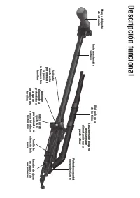
- Página 7 – Descripción funcional
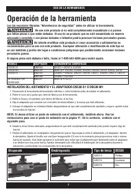
- Página 8 – Operación de la herramienta; INSTALACIÓN DEL ADITAMENTO y EL ADAPTADOR DS530-S1 O DS530-M1; bloqueado
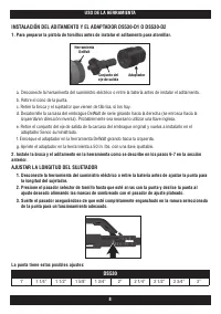
- Página 9 – INSTALACIÓN DEL ADITAMENTO y EL ADAPTADOR DS530-D1 O DS530-D2; AjUSTAR LA LONGITUD DEL SUjETADOR
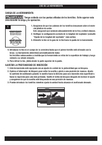
- Página 10 – CARGA DE LA hERRAMIENTA; AjUSTAR LA PROfUNDIDAD DE INSERCIÓN
- Página 11 – INSERCIÓN DE LOS TORNILLOS; OPERACIÓN INVERSA
- Página 12 – REMPLAZO DE LA PUNTA
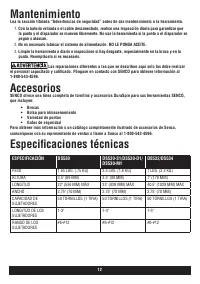
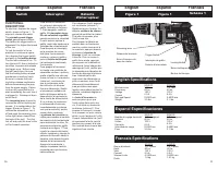
- Página 13 – Especificaciones técnicas; ESPECIFICACIÓN
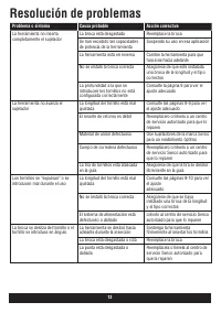
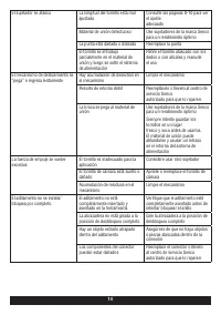
- Página 14 – Resolución de problemas
- Página 20 – ccica
- Página 23 – English Specifications
- Página 24 – OPERATION
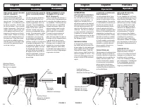
REPLACING THE BIT HOLDER
AND BIT (FIGURE 2)
Pull the locking sleeve. The
locking sleeve and adjusting
sleeve come out of the gear cas
-
ing as a set. Pull the bit holder
straight out. If it is difficult to pull
by hand, use pliers. Push a new
bit into the holder. Use a new bit
holder if necessary. Push the bit
holder (with bit) into the hex hole
of the spindle until the ball lock
snaps into the groove on the bit
holder shank. Attach the locking
sleeve (with adjusting sleeve) to
the gear case. Align the projec
-
tion inside the adjusting sleeve
with the groove of the gear case
and push the adjusting sleeve
as far as it will go.
English
Espanol
Francais
Assembly
Asamblea
Assemblée
REMPLACEMENT DU POR-
TE-EMBOUT ET DE L’EM-
BOUT (Schéma 2)
Tirez le manchon de blocage. Il
sort du carter d’engrenage avec
le manchon de réglage comme
un ensemble. Tirez le porte-em
-
bout tout droit, si c’est difficile
utilisez des pinces. Mettez un
nouvel embout dans le porte-
embout. Utilisez un nouveau
porte-embout si nécessaire.
Poussez le porte-embout et
son embout dans le trou 6
pans de l’axe jusqu’à ce que le
blocage à bille s’encastre dans
la gorge de la tige du porte-
embout. Fixez le manchon de
blocage (avec le manchon de
réglage) sur le carter d’engre
-
nages. Alignez la saillie dans
le manchon de réglage avec la
rainure du carter d’engrenages
et poussez-le à fond.
English
Espanol
Francais
Operation
Operación
Opération
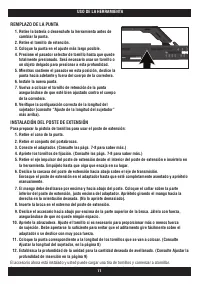
SUSTITUCION DEL ADAPTA-
DOR Y LA PUNTA (FIGURA
2)
Tire del manguito de fijación.
El manguito de fijación y el
manguito de ajuste salen de la
caja de engranajes como un
conjunto. Tire del adaptador
recto hacia afuera. Si es difícil
tirarlo con la mano, use los
alicates. Inserte una punta
nueva en el adaptador (porta
-
punta). Si es necesario, utilice
un adaptador nuevo. Inserte
el adaptador (con la punta)
en el agujero hexagonal del
husillo hasta que el bloqueo
esférico encaje en la ranura de
la espiga del adaptador. Fije
el manguito de fijación (con el
manguito de ajuste) a la caja
de engranajes. Alinee la pro
-
yección dentro del manguito
de ajuste con la ranura de la
caja de engranajes y empuje
el manguito de ajuste hasta
donde tope.
Bit Holder
Adaptador
Manchon de blocage
Adjusting Sleeve
Manguito de ajuste
Manchon de réglage
Bit
Punta
Embout
Locking Sleeve
Manguito de fijación
Porte-embout
AJUSTE DE LA PROFUNDI-
DAD (FIGURA 3)
La nariz ajustable de la herra
-
mienta atornillará automática
-
mente un tornillo hasta una pro
-
fundidad prefijada. Para ajustar
el destornillador de manera que
atornille los tornillos hasta la
profundidad deseada, desblo
-
quee el manguito de fijación,
gire el manguito de ajuste hasta
obtener la profundidad para los
adaptadores (portapuntas) o la
profundidad del tornillo. Pruebe
atornillar un tornillo en material
de descarte para determinar si
el tornillo queda correctamente
asentado. Probablemente será
necesario un ajuste adicional
para aumentar o disminuir la
profundidad del tornillo.
PARA ATORNILLAR
Para engranar el embrague para
atornillar, coloque el tornillo en
la punta y alinéelo en la posición
deseada contra la superficie de
trabajo. Oprima el gatillo. Con
el motor funcionando, empuje
la herramienta hacia adelante
para engranar el embrague.
El embrague se desengranará
cuando el tornillo se inserta a la
profundidad fijada.
OPERATION
SETTING DEPTH (FIGURE 3)
The adjustable nose piece of
the tool will automatically drive
a screw to a preset depth. To
adjust your screwdriver so it
will drive screws to the desired
depth unlock the locking sleeve,
turn the adjusting sleeve until
depth for bit holders or depth is
obtained. Test drive a fastener
in scrap materials to determine
if fastener is correctly seating.
Further adjustment may be nec
-
essary to increase or decrease
the fastener depth.
DRIVING SCREWS
To engage the clutch to drive
the screw, set the screw in the
bit and align it in the desired po
-
sition against the work surface.
Depress the trigger. With the
motor running, push the tool for
-
ward to engage the clutch. The
clutch will disengage when the
screw is driven to the selected
depth.
RÉGLAGE DE PROFON-
DEUR (Schéma 3)
Le nez réglable de l’outil amè
-
nera automatiquement la vis à
la profondeur préréglée. Pour
régler votre tournevis afin qu’il
enfonce les vis d’une certaine
longueur, débloquez le man
-
chon de blocage, tournez le
manchon de réglage jusqu’à
l’obtention de la profondeur
du porte-embout. Testez la
mise en place d’une fixation
dans un matériau d’essai pour
constater si le positionne
-
ment est le bon. Il peut être
nécessaire d’affiner le réglage
pour augmenter ou diminuer la
profondeur d’enfoncement de
l’attache.
VISSAGE DE VIS
Mettez la vis sur l’embout et
alignez-la dans à l’endroit
voulu sur la surface de travail.
Appuyez sur la détente. Avec
le moteur activé, poussez
l’outil vers l’avant pour enga
-
ger l’embrayage. L’embrayage
va se désengager quand la
vis aura été enfoncée de la
longueur prédéterminée.
Locking Sleeve
Manguito de fijación
Manchon de blocage
Adjusting Sleeve
Manguito de ajuste
Manchon de réglage
12
13
FIGURE 2
FIGURE 3
"Cargando la instrucción" significa que debes esperar hasta que el archivo se cargue y puedas leerlo en línea. Algunas instrucciones son muy grandes y el tiempo de carga depende de la velocidad de tu conexión a Internet.
Resumen
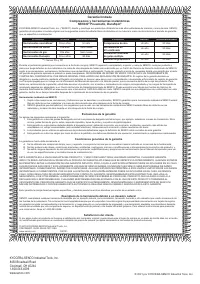
KYOCERA-SENCO Industrial Tools, Inc. 8450 Broadwell Road Cincinnati, OH 45244 1-800-543-4596 www.senco.com © 2021 por KYOCERA-SENCO Industrial Tools, Inc. NFD810X • Emitido el 13 de junio de 2021 Serie DS530 ADITAMENTO DEL SISTEMA DE ALIMENTACIÓN AUTOMÁTICA DE TORNILLOS Instrucciones de operación IM...
Índice Advertencias generales de seguridad al usar herramientas eléctricas .................................................. 4 Seguridad en el área de trabajo .............................................................................................................. 4 Seguridad con la electricid...
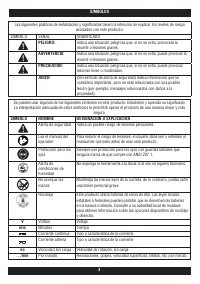
Advertencias generales de seguridad al usar herramientas eléctricas Lea todas las advertencias de seguridad, instrucciones, ilustraciones y especificaciones que se le proporcionan con esta herramienta eléctrica. El incumplimiento de todas las instrucciones enumeradas a continuación puede pr...
Otros modelos de controladores de impacto Senco
-
 Senco 10B0001N
-
 Senco 10D0001N
-
 Senco 10F0001N