Câbler le ventilateur | Cablear el ventilador; Route 0–10 V wiring into downrod and connect to 0–10 V wires; before securing downrod to fan; Route 0–10 V wiring through mounting plate and connect to 0–10 V; Fan 0–10 V Input Channel - Big Ass Fans MK-I61-051800A729S2 - Manual de uso - Página 27
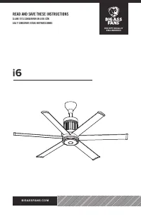

Índice:
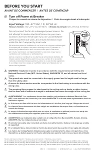
- Página 2 – BEFORE YOU START; AVANT DE COMMENCER | ANTES DE COMENZAR; ☑ Turn off Power at Breaker
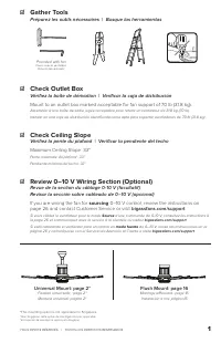
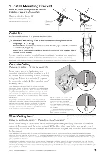
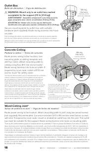
- Página 4 – Concrete Ceiling; Plafond en béton | Techo de concreto; Outlet Box; Boîte de dérivation | Caja de distribución; Install Mounting Bracket
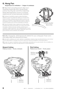
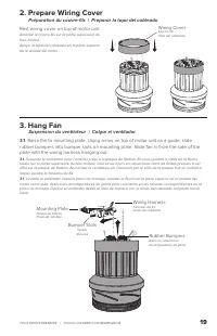
- Página 8 – Prepare Wiring Cover and Trim; Insert wiring; Sloped Ceiling; Plafond incliné | Techo inclinado; Flat Ceiling; Plafond non incliné | Techo plano
- Página 9 – Raise fan to mounting bracket. Align rib in; Power wires; Suspension du ventilateur | Colgar el ventilador
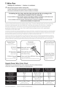
- Página 10 – Câblage du ventilateur | Cablear el ventilador; Supply Power; Australia; Supply Power Wire Color Chart
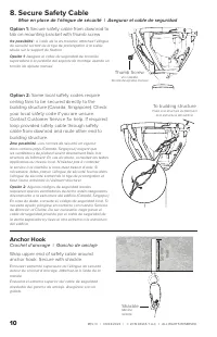
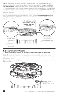
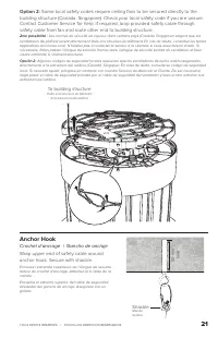
- Página 11 – Secure Safety Cable; Anchor Hook; Crochet d’ancrage | Gancho de anclaje
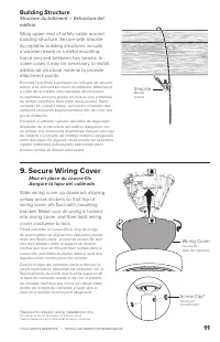
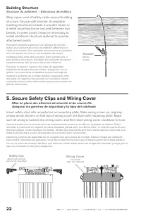
- Página 12 – Secure Wiring Cover; Building Structure; Shackle
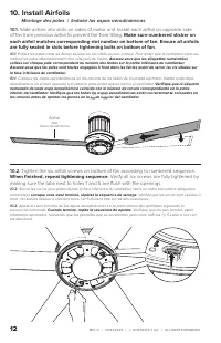
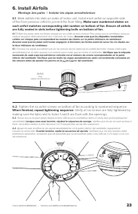
- Página 13 – Montage des pales | Instalar las aspas aerodinámicas; of fan from previous airfoil to prevent fan from tilting.; Make sure numbered sticker on; When fi nished, repeat tightening sequence.; Verify all six screws are fully tightened by
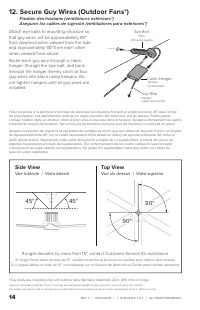
- Página 15 – Top View; Vue du dessus | Vista superior; Side View; Vue latérale | Vista lateral
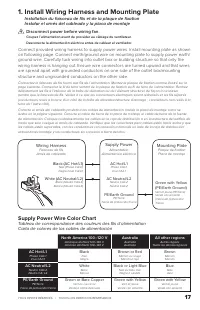
- Página 17 – Install Wiring Harness and Mounting Plate; Disconnect power before wiring fan.
- Página 18 – Wiring
- Página 20 – Ensure terminal is; Secure Safety Cable
- Página 22 – Secure Safety Clips and Wiring Cover; Safety Clip; Structure du bâtiment | Estructura del edifi cio
- Página 26 – –10 V Wiring (for fans ordered with 0–10 V option); controller supplying a 0–10 V signal.; Make sure each controller has a maximum current
- Página 27 – Câbler le ventilateur | Cablear el ventilador; Route 0–10 V wiring into downrod and connect to 0–10 V wires; before securing downrod to fan; Route 0–10 V wiring through mounting plate and connect to 0–10 V; Fan 0–10 V Input Channel
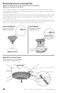
- Página 28 – Removing Covers and Light Kit; Universal Mount
TOUS DROITS RÉSERVÉS.
|
TODOS LOS DERECHOS RESERVADOS.
27
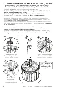
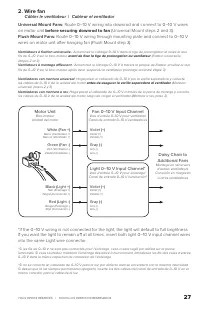
2. Wire fan
Câbler le ventilateur | Cablear el ventilador
Universal Mount Fans:
Route 0–10 V wiring into downrod and connect to 0–10 V wires
on motor unit
before securing downrod to fan
(Universal Mount steps 2 and 3).
Flush Mount Fans:
Route 0–10 V wiring through mounting plate and connect to 0–10 V
wires on motor unit after hanging fan (Flush Mount step 3).
Ventilateurs à fi xation universelle :
Acheminez le câblage 0–10 V dans la tige de prolongation et reliez-le aux
fi ls de 0–10 V sur le bloc-moteur
avant de fi xer la tige de prolongation au ventilateur
(fi xation universelle
étapes 2 et 3).
Ventilateurs à montage affl eurant :
Acheminez le câblage 0–10 V à travers la plaque de fi xation et reliez-le aux
fi ls de 0–10 V sur le bloc-moteur après avoir suspendu le ventilateur (montage encastré étape 3).
Ventiladores con montura universal:
Haga pasar el cableado de 0–10 V por la varilla separadora y conecte
los cables de 0–10 V de la unidad del motor
antes de asegurar la varilla separadora al ventilador
(Montura
universal, pasos 2 y 3).
Ventiladores con montura a ras:
Haga pasar el cableado de 0–10 V a través de la placa de montaje y conecte
los cables de 0–10 V de la unidad del motor luego de colgar el ventilador (Montura a ras, paso 3).
White (Fan +)
Blanc (Ventilateur +)
Blanco (Ventilador +)
Green (Fan -)
Vert (Ventilateur -)
Verde (Ventilador -)
Fan 0–10 V Input Channel
Voie d’entrée 0–10 V pour ventilation
Canal de entrada 0–10 V ventiladores
Motor Unit
Bloc-moteur
Unidad del motor
Violet (+)
Violet (+)
Violeta (+)
Gray (-)
Gris (-)
Gris (-)
Light 0–10 V Input Channel*
Voie d’entrée 0–10 V pour éclairage*
Canal de entrada 0–10 V iluminación*
Violet (+)
Violet (+)
Violeta (+)
Gray (-)
Gris (-)
Gris (-)
Black (Light +)
Noir (Éclairage +)
Negro (Iluminación +)
Red (Light -)
Rouge (Éclairage -)
Rojo (Iluminación -)
Daisy Chain to
Additional Fans
Montage en série vers
d’autres ventilateurs
Conexión en margarita
a otros ventiladores
*If the 0–10 V wiring is not connected for the light, the light will default to full brightness.
If you want the light to remain off at all times, insert both light 0–10 V input channel wires
into the same Light wire connector.
*Si les fi ls de 0–10 V ne sont pas connectés pour l'éclairage, celui-ci sera réglé par défaut sur la pleine
luminosité. Si vous souhaitez maintenir l'éclairage désactivé à tout moment, introduisez les fi ls des voies d'entrée
0–10 V dans le même capuchon de connexion de l'éclairage.
*Si no se conecta un cableado de 0–10 V para la luz, por defecto esta se encenderá con la máxima intensidad.
Si desea que la luz siempre permanezca apagada, inserte los dos cables del canal de entrada de 0–10 V en el
mismo conector para el cable de la luz.
"Cargando la instrucción" significa que debes esperar hasta que el archivo se cargue y puedas leerlo en línea. Algunas instrucciones son muy grandes y el tiempo de carga depende de la velocidad de tu conexión a Internet.
Resumen
REV. O | 09/22/2022 | © 2019 DELTA T LLC Ι ALL RIGHTS RESERVED. WARNING: Installation must be in accordance with the requirements set forth by the National Electrical Code (NEC, United States), ANSI/NFPA 70, and all national and local codes.The ground wire must be connected to the supply grou...
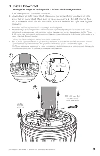
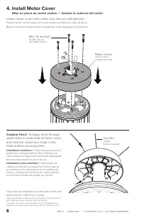
TOUS DROITS RÉSERVÉS. | TODOS LOS DERECHOS RESERVADOS. 3 Concrete Ceiling Plafond en béton | Techo de concreto Route power wiring to fan location. Use mounting bracket as drilling template and drill four holes. Attach mounting bracket to ceiling using four Ø 6 mm anchor bolts*. If required by loca...
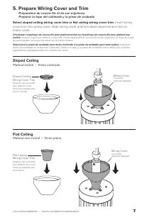
TOUS DROITS RÉSERVÉS. | TODOS LOS DERECHOS RESERVADOS. 7 5. Prepare Wiring Cover and Trim Préparation du couvre-fils et de son enjoliveurPreparar la tapa del cableado y la pieza de acabado Select sloped ceiling wiring cover trim or flat ceiling wiring cover trim. Insert wiring cover trim into wiri...
Otros modelos de ventiladores de techo Big Ass Fans
-
 Big Ass Fans FR127C-U1H00-3L0209258-532P610
-
Big Ass Fans MK-HK4-04240001A258F221G10
-
Big Ass Fans MK-HK4-04240001A258F222G10
-
Big Ass Fans MK-HK4-04240001A259F221G10
-
Big Ass Fans MK-HK4-04240001A470F221G10
-
Big Ass Fans MK-HK4-04240001A470F222G10
-
Big Ass Fans MK-HK4-04240001A471F221G10
-
Big Ass Fans MK-HK4-04240001A471F222G10
-
Big Ass Fans MK-HK4-042400A258F258G10
-
Big Ass Fans MK-HK4-042400A259F259G10