/4” CUSTOM DECORATIVE PANEL DIMENSIONS; Design Guide - Custom Overlay Door Panel; CUSTOM HANDLE DESIGN GUIDE; Door Trim Pinch Point - Monogram ZIR361NPRII - Manual de uso - Página 21

Frigorífico Monogram ZIR361NPRII - Manual de uso, léela gratuitamente en línea en formato PDF. Esperamos que esto te ayude a resolver cualquier duda que puedas tener. Si tienes más preguntas, contáctanos a través del formulario de contacto.


Índice:
- Página 2 – ANTES DE COMENZAR; IMPORTANTE; PRECAUCIÓN; ADVERTENCIA; FORMA ADECUADA DE DESCARTAR SU ELECTRODOMÉSTICO
- Página 4 – Installation Instructions - Reversing the Door Swing; WARNING; Risque de
- Página 5 – STEP 2 REMOVE DOOR; Door Hinge Pinch
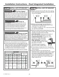
- Página 8 – STEP 4 INSTALL ANTI-TIP BRACKET; Dual install
- Página 9 – Electrical Shock Hazard.; Trisque de
- Página 10 – ON; STEP 12 START ICEMAKER; OFF; CAUTION; ATTENTION
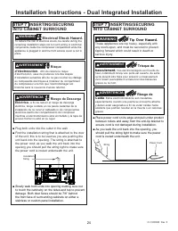
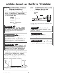
- Página 13 – STEP 7 INSERTING/SECURING INTO
- Página 17 – STEP 11 START ICEMAKER (freezer models)
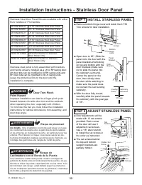
- Página 19 – Installation Instructions - Stainless Door Panel; Door Trim Pinch; STEP 1 INSTALL STAINLESS PANEL; Risque de pincement
- Página 21 – /4” CUSTOM DECORATIVE PANEL DIMENSIONS; Design Guide - Custom Overlay Door Panel; CUSTOM HANDLE DESIGN GUIDE; Door Trim Pinch Point
64
31-1000600 Rev. 0
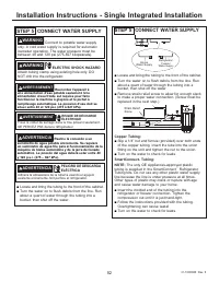
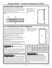
3/4” CUSTOM DECORATIVE PANEL DIMENSIONS
For a more custom appearance, overlay panels may be
installed to give a flush appearance with surrounding cabinets.
The overlay panel must be 3/4” (1.91cm) thick. Panel attaches
to included brackets to provide mounting to the appliance door.
NOTE:
We recommend that decorative panels have inside
corners and edges rounded or beveled by cabinet maker to
avoid sharp edges on the panels. Edges to be treated should
include the top, bottom and hinge side edges.
IMPORTANT NOTE:
Maximum panel weight is 45 lbs.
NOTE:
For panels constructed with rails and stiles (5-panel), the
rails and stiles must be a minimum of 2” (5.08cm) wide.
For Stainless Panel Kits,
see Stainless Steel Door Panel
Installation on page 45.
For Custom Panels,
use templates provided with the units to
pre-drill holes for mounting panel brackets (provided with unit).
Adjustment screws and instructions are provided.
Design Guide - Custom Overlay Door Panel
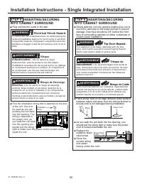
CUSTOM HANDLE DESIGN GUIDE
Custom handles must be used for flush installation. For
custom handle installation, counter-bore holes in rear of
decorative panels must ensure 1/2” (1.27cm) material
thickness remains for handle support.
NOTE:
The counterbore must not exceed 1” (2.54cm) in
diameter.
Minimum distance from
panel side edge to
handle center should
be 1-1/2” (3.81 cm) as
shown.
1/4"
(0.64cm)
1/2"
(1.27cm)
3/4"
(1.91cm)
Door
Panel
B
A
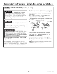
WARNING
d
Door Trim Pinch Point
Hazard
Improper installation can lead to a finger pinch point hazard
between the side door trim and the cabinets when operating
the door, especially with children. To minimize this risk you
must follow the installation instructions for cabinet dimen-
sions, trim assembly, and door stop angle.
Panel
Dimension
18” Models
24” Models
30” Models
A
17-9/16”
(44.61cm)
23-9/16”
(59.85cm)
29-9/16”
(75.09)
B
79-7/8”
(202.88cm)
79-7/8”
(202.88cm)
79-7/8”
(202.88cm)
IMPORTANT:
Custom decorative
door panel width dimensions are
GLႇHUHQWIRUVLQJOHPRGHODQG
dual model installations.
1-1/2”
Hinge
Side
Handle
Side
AVERTISSEMENT
d
Risque de pincement
de doigts.
IUne installation incorrecte peut poser un risque
de coincement de doigts entre la garniture de porte latérale
et les armoires en manipulant la porte, en particulier pour
les enfants. Pour réduire ce risque, vous devez suivre les
instructions d’installation relatives aux dimensions d’armoire,
au montage des garnitures et à l’angle de l’arrêt de porte.
ADVERTENCIA
d
Riesgo de
Lastimadura con el Borde de la Puerta
Una instalación inadecuada puede conducir a riesgos de
pellizcos de dedos entre el borde lateral de la puerta y
los gabinetes al utilizar la puerta, especialmente con los
niños. A fin de minimizar este riesgo, usted deberá seguir
las instrucciones de instalación para dimensiones de
gabinetes, ensambles de bordes y ángulos de detención de
puertas.
"Cargando la instrucción" significa que debes esperar hasta que el archivo se cargue y puedas leerlo en línea. Algunas instrucciones son muy grandes y el tiempo de carga depende de la velocidad de tu conexión a Internet.
Resumen
4 31-1000600 Rev. 0 Safety Information ANTES DE COMENZAR Lea estas instrucciones en su totalidad y atentamente. • IMPORTANTE – Conserve estas instrucciones para uso del inspector local. Cumpla con todos los códigos y ordenanzas gubernamentales. • Nota para el Instalador – Asegúrese de que el Com...
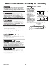
9 31-1000600 Rev. 0 Installation Instructions - Reversing the Door Swing STEP 1 REMOVE UPPER ENCLOSURE Ŷ Open the front cover of the enclosure to 90°. Locate filter and filter removal tool. Filter should be as shown. Ŷ 5RWDWH¿OWHUóWXUQ counterclockwise (use ¿OWHUUHPRYDOWRROLI needed). Ŷ 3XOO¿OWHUWR...
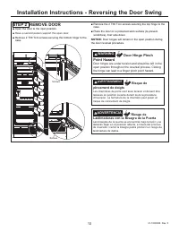
10 31-1000600 Rev. 0 Installation Instructions - Reversing the Door Swing STEP 2 REMOVE DOOR Ŷ Open the door to the open position. Ŷ Have a second person support the open door. Ŷ Remove 2 T30 Torx screws securing the bottom hinge to the case. Ŷ Remove the 2 T30 Torx screws securing the top hinge...