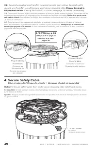
–10 V Wiring (for fans ordered with 0–10 V option); controller supplying a 0–10 V signal.; Make sure each controller has a maximum current - Big Ass Fans MK-I61-051800A729 - Manual de uso - Página 26


Índice:
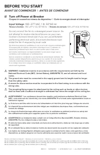
- Página 2 – BEFORE YOU START; AVANT DE COMMENCER | ANTES DE COMENZAR; ☑ Turn off Power at Breaker
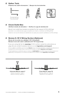
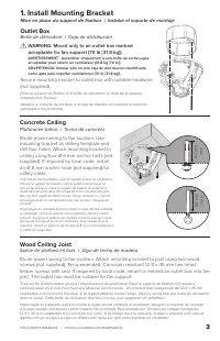
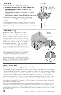
- Página 4 – Install Mounting Bracket; Outlet Box; Boîte de dérivation | Caja de distribución; Concrete Ceiling; Plafond en béton | Techo de concreto; Wood Ceiling Joist; Solive de plafond en bois | Viga de techo de madera
- Página 5 – Ground Wire
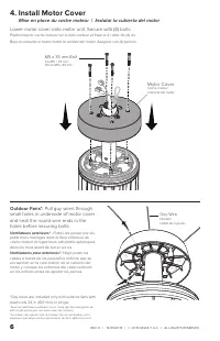
- Página 7 – Install Motor Cover; Mise en place du cache moteur | Instalar la cubierta del motor; Motor Cover
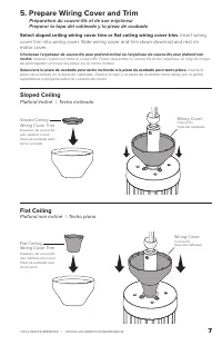
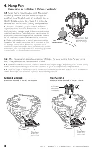
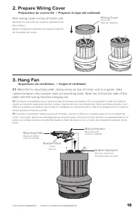
- Página 8 – Prepare Wiring Cover and Trim; Insert wiring; Sloped Ceiling; Plafond incliné | Techo inclinado; Flat Ceiling; Plafond non incliné | Techo plano
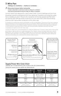
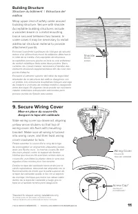
- Página 9 – Raise fan to mounting bracket. Align rib in; Power wires; Suspension du ventilateur | Colgar el ventilador
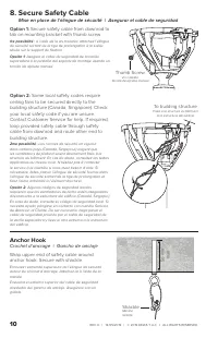
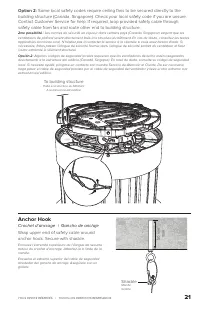
- Página 11 – Secure Safety Cable; Anchor Hook; Crochet d’ancrage | Gancho de anclaje
- Página 12 – Secure Wiring Cover; Building Structure; Shackle
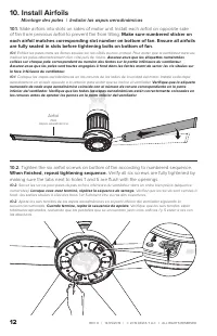
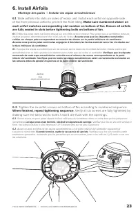
- Página 13 – Montage des pales | Instalar las aspas aerodinámicas; of fan from previous airfoil to prevent fan from tilting.; Make sure numbered sticker on; When finished, repeat tightening sequence.; Verify all six screws are fully tightened by
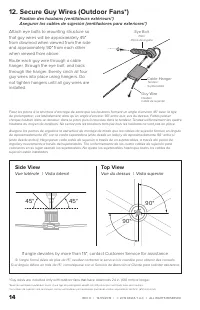
- Página 15 – Top View; Vue du dessus | Vista superior; Side View; Vue latérale | Vista lateral
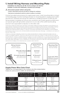
- Página 17 – Install Wiring Harness and Mounting Plate; Disconnect power before wiring fan.
- Página 18 – Wiring
- Página 20 – Ensure terminal is; Secure Safety Cable
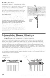
- Página 22 – Secure Safety Clips and Wiring Cover; Safety Clip; Structure du bâtiment | Estructura del edificio
- Página 26 – –10 V Wiring (for fans ordered with 0–10 V option); controller supplying a 0–10 V signal.; Make sure each controller has a maximum current
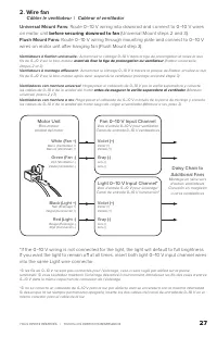
- Página 27 – Câbler le ventilateur | Cablear el ventilador; Route 0–10 V wiring into downrod and connect to 0–10 V wires; before securing downrod to fan; Route 0–10 V wiring through mounting plate and connect to 0–10 V; Fan 0–10 V Input Channel
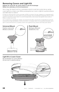
- Página 28 – Removing Covers and Light Kit; Universal Mount
REV. D | 12/05/2019 | © 2019 DELTA T LLC Ι ALL RIGHTS RESERVED.
26
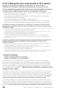
0–10 V Wiring (for fans ordered with 0–10 V option)
Câblage 0-10 V (pour les ventilateurs commandés avec l'option 0-10 V)
Cableado de 0–10 V (para ventiladores encargados con la opción de 0–10 V)
The fan and light are programmed for sinking 0–10 V control by default. To change to
sourcing control, contact Customer Service or visit bigassfans.com/support
• When the fan is wired for 0–10 V control, all other fan controls, including the remote
control and mobile app, are disabled.
• Input signal is job dependent and could be a 0–10 V wall dimmer or automation
controller supplying a 0–10 V signal.
• Use solid or stranded wire: 20–14 AWG / 0.518–2.08 mm
2
• The number of fans that can be daisy chained depends on the 0–10 V controller
load. We do not recommend daisy chaining more than ten fans to one controller.
Le ventilateur et l'éclairage sont programmés en mode Sink pour la commande de 0–10 V par défaut.
Pour basculer sur le mode Source de la commande, communiquez avec le service à la clientèle ou visitez
bigassfans.com/support
• Lorsque le ventilateur est câblé pour une commande de 0–10 V, toutes les autres commandes de ventilateur,
y compris la télécommande et l'application mobile, sont désactivées.
• Le signal d’entrée est dépendant de l’opération ; il peut s’agir d’un gradateur mural de 0–10 V ou d’un
dispositif de commande d’automatisation délivrant un signal de 0–10 V.
• Utilisez des fils rigides ou multibrins : 20 à 14 AWG / 0,518–2,08 mm
2
• Le nombre de ventilateurs qui peuvent être montés en série dépend de la charge du dispositif de
commande de 0–10 V. Nous ne recommandons pas de configurer en série plus de dix ventilateurs par
dispositif de commande.
Por defecto, el ventilador y la luz están programados para un control de 0–10 V en modo sumidero. Para
cambiar a control en modo fuente, comuníquese con el Servicio de Atención al Cliente o visite
bigassfans.com/support
• Cuando el ventilador esté cableado para control de 0–10 V, todos los demás controles del ventilador
quedarán deshabilitados, incluyendo el control remoto y la aplicación móvil.
• La señal de entrada depende de cada tarea y podría ser un atenuador de pared o un controlador de
automatización de 0–10 V que proporcione una señal de 0–10 V.
• Utilice cable macizo o trenzado: 20–14 AWG / 0.518–2.08 mm
2
• La cantidad de ventiladores que se pueden conectar en margarita depende de la carga del controlador de
0–10 V. No recomendamos conectar en margarita más de diez ventiladores a un controlador.
1. Install controller(s)
Installer le(s) dispositif(s) de commande
Instalar el controlador o los controladores
Fans wired for 0–10 V control require two separate 0–10 V channels for light and
fan control. For full functionality, two wall controllers are required, or one automation
controller with multiple 0–10 V channels is required. Consult the instructions included
with the wall controller or automation controller you are installing for product specific
wiring diagrams and specifications.
Make sure each controller has a maximum current
capacity of 2 mA or higher.
Les ventilateurs câblés pour une commande de 0–10 V exigent deux voies 0–10 V distinctes pour la commande
du ventilateur et de l'éclairage. Pour un fonctionnement optimal, il convient de prévoir soit deux dispositifs de
commande muraux, soit un dispositif de commande d’automatisation doté de plusieurs voies 0–10 V. Veuillez vous
reporter à la notice fournie avec le dispositif de commande mural ou le dispositif de commande d’automatisation
que vous installez pour consulter les caractéristiques et les schémas électriques propres à ce produit.
Assurez-
vous que chaque dispositif de commande a une intensité admissible maximale de 2 mA ou plus.
Los ventiladores cableados para control de 0–10 V requieren dos canales de 0–10 V diferentes para controlar
la luz y el ventilador. Para lograr la máxima funcionalidad, se requieren dos controladores, o un controlador para
automatización con múltiples canales de 0–10 V. Consulte las instrucciones incluidas con el controlador de pared
o el controlador de automatización que esté instalando para ver los diagramas de cableado y las especificaciones
del producto.
Asegúrese de que cada controlador tenga una capacidad de corriente máxima de 2 mA o más.
"Cargando la instrucción" significa que debes esperar hasta que el archivo se cargue y puedas leerlo en línea. Algunas instrucciones son muy grandes y el tiempo de carga depende de la velocidad de tu conexión a Internet.
Resumen
REV. D | 12/05/2019 | © 2019 DELTA T LLC Ι ALL RIGHTS RESERVED. WARNING: Installation must be in accordance with the requirements set forth by the National Electrical Code (NEC, United States), ANSI/NFPA 70, and all national and local codes.The ground wire must be connected to the supply grou...
TOUS DROITS RÉSERVÉS. | TODOS LOS DERECHOS RESERVADOS. 3 1. Install Mounting Bracket Mise en place du support de fixation | Instalar el soporte de montaje Outlet Box Boîte de dérivation | Caja de distribución WARNING: Mount only to an outlet box marked acceptable for fan support (70 lb [31.8 kg])....
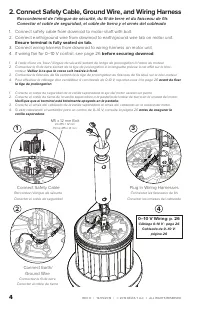
REV. D | 12/05/2019 | © 2019 DELTA T LLC Ι ALL RIGHTS RESERVED. 4 2. Connect Safety Cable, Ground Wire, and Wiring Harness Raccordement de l’élingue de sécurité, du fil de terre et du faisceau de filsConectar el cable de seguridad, el cable de tierra y el arnés del cableado 1. Connect safety ...
Otros modelos de ventiladores de techo Big Ass Fans
-
 Big Ass Fans FR127C-U1H00-3L0209258-532P610
-
Big Ass Fans MK-HK4-04240001A258F221G10
-
Big Ass Fans MK-HK4-04240001A258F222G10
-
Big Ass Fans MK-HK4-04240001A259F221G10
-
Big Ass Fans MK-HK4-04240001A470F221G10
-
Big Ass Fans MK-HK4-04240001A470F222G10
-
Big Ass Fans MK-HK4-04240001A471F221G10
-
Big Ass Fans MK-HK4-04240001A471F222G10
-
Big Ass Fans MK-HK4-042400A258F258G10
-
Big Ass Fans MK-HK4-042400A259F259G10